 Printable View (125 KB) Printable View (125 KB)
|
TSB
13-7-7 |
- 4X4 WITH 145-INCH WHEELBASE - CLICK/SNAP NOISE ON INITIAL ACCELERATION FROM A STOP
|
| Publication Date: July 15, 2013 |
The article supersedes TSB 12-11-17 to update the vehicle model years, Part List and Service Procedure.
ISSUE:
Some 2012-2013 F-150 4x4 vehicles with a 145-inch wheelbase may exhibit an intermittent click or snap-type noise from the rear axle on initial light acceleration from a stop in either drive or reverse. The noise may also occur on light acceleration after changing direction from drive to reverse, or reverse to drive.
ACTION:
Follow the Service Procedure steps to correct the condition.
SERVICE PROCEDURE
- Does vehicle exhibit a single click or snap-type noise from the rear axle on light acceleration after the initial engagement into Drive or Reverse, or after stopping to reverse vehicle direction?
- Yes - noise is present, proceed to Step 2.
- No - this article does not apply. Refer to Workshop Manual (WSM), Section 205-00 for normal diagnostics.
- Is the noise heard at the rear driveshaft u-joint area?
- Yes - apply a few drops of Motorcraft® Penetrating and Lock Lubricant to each of the driveshaft universal joint retaining clips and wipe off excess and retest. If the noise is resolved repair is complete release vehicle to the customer. If the noise is still present proceed to Step 3.
- No - proceed to Step 3.
- With the vehicle in neutral, position it on a hoist. For additional information, refer to WSM, Section 100-02.
- Index-mark the driveshaft flange and pinion flange for correct alignment during installation. (Figure 1)

Figure 1 - Article 13-7-7
- Remove and discard the four (4) driveshaft flange bolts.
- Disconnect the driveshaft centering socket yoke from the pinion flange. (Figure 2)
- The driveshaft centering socket yoke fits tightly on the pinion flange pilot. Never hammer on the driveshaft or any of its components to disconnect the driveshaft centering socket yoke from the pinion flange. Pry only in the area shown with a suitable tool to disconnect the driveshaft centering socket yoke from the pinion flange.
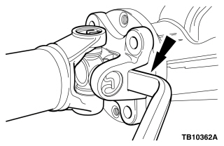
Figure 2 - Article 13-7-7
- Support and position the driveshaft aside.
- Remove rear disc brake calipers and support them out of the way to allow the axles to rotate freely. Refer to WSM, Section 206-04.
- It is not necessary to remove the brake lines from the brake calipers for this procedure.
- Rotate the rear axle pinion and record the turning torque with the differential and axle shafts installed.
- Remove the rear pinion flange, pinion seal, and oil slinger. Refer to WSM, Section 205-02B, In-Vehicle Repair, Drive Pinion Flange and Drive Pinion Seal.
- It is critical to follow the WSM procedure to press the pinion flange off and on to prevent damage to the pinion flange.
- Inspect the oil slinger for signs of wear. Are there signs of wear present?
- Yes - replace the slinger, proceed to Step 12.
- No - proceed to Step 12.
- Lubricate both faces of the slinger with Motorcraft® Premium Long-Life Grease.
- Install slinger, pinion seal, and pinion flange. Refer to WSM, Section 205-02B.
- Adjust rear pinion preload to ± 0.14 kg·cm (2 lb-in) from the initial pinion turning torque taken in Step 9.
- Used bearings require a lower preload than new bearings.
- Install rear disc brake calipers. Refer to WSM, Section 206-04.
- Position the driveshaft to the pinion flange and align the index marks. (Figure 1)
- Install four (4) new driveshaft flange bolts and tighten to 103 N-m (76 lb-ft).
- If new bolts are not available, coat the threads of the original driveshaft flange bolts with Motorcraft® Threadlock and Sealer.
- The driveshaft centering socket yoke fits tightly on the pinion flange pilot. To make sure the driveshaft centering socket yoke seats squarely on the pinion flange, tighten the driveshaft flange bolts evenly in a cross pattern.
WARRANTY STATUS:
Eligible Under Provisions Of New Vehicle Limited Warranty Coverage
Warranty/ESP coverage limits/policies/prior approvals are not altered by a TSB. Warranty/ESP coverage limits are determined by the identified causal part and verified using the OASIS part coverage tool.
| OPERATION |
DESCRIPTION |
TIME |
| 130707A | 2012-2013 F-150 4X4: Lubricate Retaining Clips Concern Resolved Includes Time For Road Tests (Do Not Use With Any Other Labor Operations) | 0.8 |
| 130707B | 2012-2013 F-150 4X4: Lubricate Retaining Clips Concern Not Resolved Follow Service Procedure To Adjust Pinion Bearing Preload Includes Time To Replace The Oil Slinger If Necessary And Road Tests (Do Not Use With Any Other Labor Operations) | 1.7 Hrs. |
DEALER CODING
| BASIC PART NO. |
CONDITION CODE |
| 4670 |
41 |
NOTE: The information in Technical Service Bulletins is intended for use by trained, professional technicians with the knowledge, tools, and equipment to do the job properly and safely. It informs these technicians of conditions that may occur on some vehicles, or provides information that could assist in proper vehicle service. The procedures should not be performed by "do-it-yourselfers". Do not assume that a condition described affects your car or truck. Contact a Ford or Lincoln dealership to determine whether the Bulletin applies to your vehicle. Warranty Policy and Extended Service Plan documentation determine Warranty and/or Extended Service Plan coverage unless stated otherwise in the TSB article. The information in this Technical Service Bulletin (TSB) was current at the time of printing. Ford Motor Company reserves the right to supercede this information with updates. The most recent information is available through Ford Motor Company's on-line technical resources.
Copyright © 2013 Ford Motor Company