
This view of the Owner's Manual contains the very latest information, which may vary slightly from the printed Owner's Manual originally provided with your vehicle. It may also describe content that is not on or operates differently on your vehicle. Please consider the Owner's Manual originally provided with your vehicle as the primary source of information for your vehicle.

The information contained in this publication was correct at the time of release.In the interest of continuous development, we reserve the right to change specifications, design or equipment at any time without notice or obligation.No part of this publication may be reproduced, transmitted, stored in a retrieval system or translated into any language in any form by any means without our written permission.Errors and omissions excepted.
Copyright © 2024 Ford Motor Company
Essential Towing Checks
Follow these guidelines for safe towing:

 WARNING:
Do not exceed the maximum vertical load on the tow ball. Failure to follow this instruction could result in the loss of control of your vehicle, personal injury or death.
WARNING:
Do not exceed the maximum vertical load on the tow ball. Failure to follow this instruction could result in the loss of control of your vehicle, personal injury or death. |
Follow these guidelines for safe towing:
- Do not tow a trailer until you drive your vehicle at least 1,000 mi (1,600 km).
- Consult your local motor vehicle laws for towing a trailer.
- See the instructions included with towing accessories for the proper installation and adjustment specifications.
- Service your vehicle more frequently if you tow a trailer. See your scheduled maintenance information. See Scheduled Maintenance.
- If you use a rental trailer, follow the instructions the rental agency gives you.
See Load Limits in the Load Carrying chapter for load specification terms found on the tire label and Safety Compliance label and instructions on calculating your vehicle's load.
Vehicles with a diesel engine have an engine braking feature. See
General Information.
Remember to account for the trailer tongue weight as part of your vehicle load when calculating the total vehicle weight.
Some vehicles will have the ability to modify trailer towing features. See
General Information.
Trailer Towing Connector
When attaching the trailer wiring connector to your vehicle, only use a proper fitting connector that works with the vehicle and trailer functions. Some seven-position connectors may have the SAE J2863 logo, which confirms that it is the proper wiring connector and works correctly with your vehicle.
| Color | Function |
|---|---|
| Yellow | Left turn signal and stop lamp |
| White | Ground (-) |
| Blue | Electric brakes |
| Green | Right turn signal and stop lamp |
| Orange | Battery (+) |
| Brown | Running lights |
| Grey | Reverse lights |
Note:
If your vehicle is equipped with a factory brake controller, the Battery (+) Orange wire is powered when you start the engine and you apply the brakes at least once when a trailer with brake lamps is connected. If your vehicle is not equipped with a factory brake controller, relays control the system and it becomes active when you power on your vehicle.
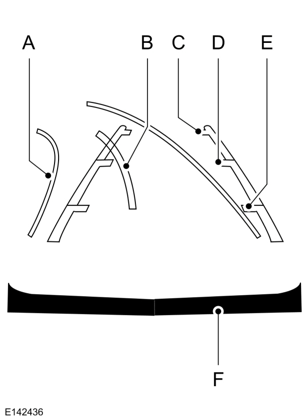
Dynamic Hitching Using the Rear View Camera System
Note:
Active guidelines and fixed guidelines are only available when the transmission is in reverse (R).
Use the centerline (B) guideline to assist you in setting your steering wheel properly to help align the trailer hitch and tongue.
| A B C D E F |
Fixed guidelines are always shown in the display, but the active guidelines only display when the steering wheel is turned.To use active guidelines, turn the steering wheel to point the guidelines toward an intended path.If the steering wheel position is changed while reversing, your vehicle might deviate from the original intended path.
The active guidelines fade in and out depending on the steering wheel position. The active guidelines are not shown when the steering wheel position is straight.
Always use caution while reversing. Objects in the red zone are closest to your vehicle and objects in the green zone are farther away. Objects are getting closer to your vehicle as they move from the green zone to the yellow or red zones. Use the side view mirrors and rear view mirror to get better coverage on both sides and rear of your vehicle.
Refer to the Rear View Camera section for additional information. See
Rear View Camera.
Hitches
Note:
On pick-up trucks, the trailer hitch provided on this vehicle enhances crash protection for the fuel system. Do not remove!
Note:
Do not cut, drill, weld or modify trailer hitches. Modifying trailer hitches can reduce hitch rating.
Do not use a hitch that either clamps onto the bumper or attaches to the axle. You must distribute the load in your trailer so that 10-15% for conventional towing or 15-25% for fifth wheel towing of the total weight of the trailer is on the tongue.
Hitch Components (If Equipped)
The following components are required. Some are provided in certain vehicles.
- A trailer hitch with a 3 inch receiver and 5/8 inch hitch pin rated to tow up to 21,000 lb (9,525 kg).
- A hitch pin sleeve stored in the glove box to be used when mounting the 3 inch drawbar.
- A cotter pin to help keep the hitch pin in place.
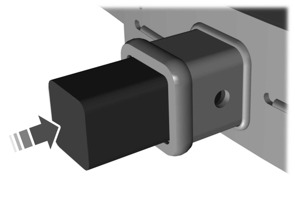
Installing a 3 Inch Drawbar with 3/4 Inch Pin Hole
The pin sleeve should be inserted in the 3/4 inch pin hole of the 3 inch drawbar.
Remove reducers before inserting the 3 inch drawbar. Insert the drawbar into hitch receiver.
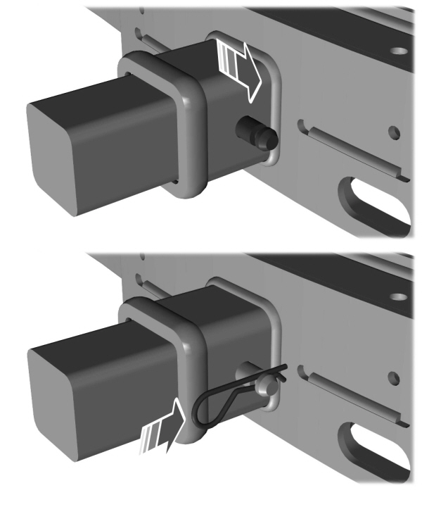
Put the 5/8 inch hitch pin through pin hole. Place the cotter pin around the neck of hitch pin.
Weight-distributing Hitches
|
WARNING:
Do not adjust the spring bars so that your vehicle's rear bumper is higher than before attaching the trailer. Doing so will defeat the function of the weight-distributing hitch, which may cause unpredictable handling, and could result in serious personal injury. |
When hooking-up a trailer using a weight-distributing hitch, always use the following procedure:
- Park the loaded vehicle, without the trailer, on a level surface.
- Measure the height to the top of your vehicle's front wheel opening on the fender. This is H1.
- Attach the loaded trailer to your vehicle without the weight-distributing bars connected.
- Measure the height to the top of your vehicle's front wheel opening on the fender a second time. This is H2.
- Install and adjust the tension in the weight-distributing bars so that the height of your vehicle's front wheel opening on the fender is approximately halfway between H1 and H2.
- Check that the trailer is level or slightly nose down toward your vehicle. If not, adjust the ball height accordingly and repeat Steps 2-6.
- Lock the bar tension adjuster in place.
- Check that the trailer tongue securely attaches and locks onto the hitch.
- Install safety chains, lighting, and trailer brake controls as required by law or the trailer manufacturer.
Fifth-wheel Trailer Hitch (If Equipped)
Note:
For a detailed description of installation and other information, see the Owner's Manual-5th Wheel Trailer Hitch.
Note:
The mounting pads in the bed are specifically designed for certain fifth-wheel trailer hitches and gooseneck ball hitches. Do not use these mounting pads for other purposes.
Note:
Contact an authorized dealer to purchase gooseneck and fifth-wheel hitches that are compatible with your vehicle.
Your vehicle may be equipped with a fifth-wheel prep package. This package enables your vehicle to accept certain fifth-wheel trailer hitches and gooseneck ball hitches. The fifth-wheel trailer hitch attaches to the four mounting pads in the pick-up bed. An optional 7-pin trailer wiring connector may be in the bed as well. The gooseneck ball hitch is a separate mounting pad from the fifth-wheel hitch, located in the center of the bed.
Shorter pick-up boxes, such as the 6½-foot box on the F-250 and F-350, provide less clearance between the cab and the fifth-wheel and gooseneck trailer compared to longer box pick-ups, such as an 8-foot box on the F-250 or F-350. When selecting a trailer and tow vehicle, it is critical to check that this combination provides clearance between the front of the trailer and tow vehicle for turns up to 90 degrees. Failure to follow this recommendation could result in the trailer contacting the cab of the tow vehicle during tight turns that are typical during low-speed parking and turning maneuvers. This contact could result in damage to the trailer and tow vehicle.
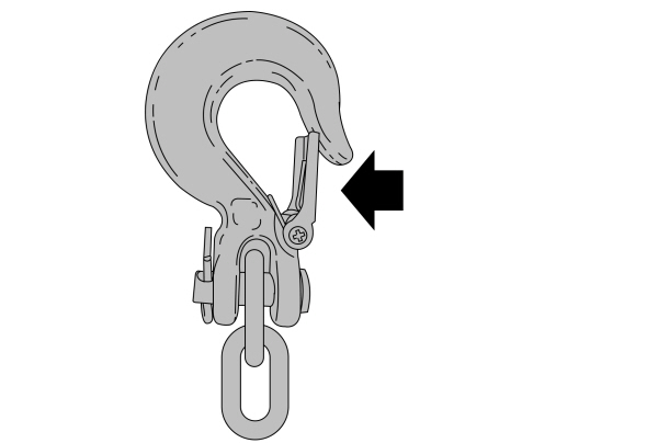
Safety Chains
Note:
Do not attach safety chains to the bumper. Always connect the safety chains to the frame or hook retainers of your trailer hitch.
Install trailer safety chains to the trailer hitch as recommended by the manufacturer. Cross the chains under the trailer tongue and allow enough slack for turning tight corners. Do not allow the chains to drag on the ground.
If the trailer safety chain hook has a latch, make sure the latch is fully closed.
Note:
If you install the hook with the latch facing toward the rear of your vehicle, you may not be able to fully close the safety chain hook latch. If this occurs, install the hook with the latch facing toward the front of your vehicle.
Trailer Brakes
|
WARNING:
Do not connect a trailer's hydraulic brake system directly to your vehicle's brake system. Your vehicle may not have enough braking power and your chances of having a collision greatly increase. |
Electric brakes and manual, automatic or surge-type trailer brakes are safe if you install them properly and adjust them to the manufacturer's specifications. The trailer brakes must meet local and federal regulations.
The rating for the tow vehicle's braking system operation is at the gross vehicle weight rating, not the gross combined weight rating.
Separate functioning brake systems are required for safe control of towed vehicles and trailers weighing more than 1500 lb (680 kg) when loaded.
Integrated Trailer Brake Controller (If Equipped)
|
WARNING:
The anti-lock brake system does not control the trailer brakes.
WARNING:
Use the integrated trailer brake controller to properly adjust the trailer brakes and check all connections before towing a trailer. Failure to follow this instruction could result in the loss of control of your vehicle, personal injury or death. |
Note:
The integrated Ford brake controller is compatible with trailers equipped with electric-actuated drum brakes and electric-over hydraulic brake systems.
Note:
The integrated Ford brake controller does not control hydraulic surge-style brakes.
When used properly, the trailer brake controller assists in smooth and effective trailer braking by powering the trailer’s electric or electric-over-hydraulic brakes with a proportional output based on the towing vehicle’s brake pressure.
You can adjust the amount of initial trailer brake output by selecting one of three settings through the message center.
Ford has tested the trailer brake controller to be compatible with several major brands of electric-over-hydraulic trailer brakes. Contact an authorized dealer for information on which brands you can use.
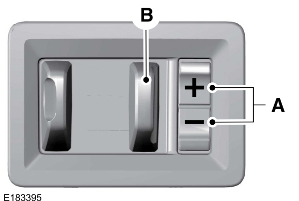
The controller user interface consists of the following:
A: + and - (Gain adjustment buttons): Pressing these buttons adjusts the controller's power output to the trailer brakes in 0.5 increments. You can increase the gain setting to 10.0 (maximum trailer braking) or decrease it to 0 (no trailer braking). Pressing and holding a button raises or lowers the setting continuously. The gain setting displays in the message center as follows: TBC GAIN = XX.X.
B: Manual control lever: Slide the control lever to the left to switch on the trailer's electric brakes independent of the tow vehicle's. See the following Procedure for adjusting gain section for instructions on proper use of this feature. If you use the manual control while the brake is also applied, the greater of the two inputs determines the power sent to the trailer brakes.
- Stop lamps: Using the manual control lever lights both the trailer brake lamps and your vehicle brake lamps.
- TBC GAIN = XX.X NO TRAILER: Shows the current gain setting.
- TBC GAIN = XX.X OUTPUT=/ / / / / /: Displays when braking. The bars indicate the amount of power going to the trailer brakes.
- TRAILER CONNECTED: Displays when the system senses a correct trailer wiring connection.
- TRAILER DISCONNECTED: Displays when the system senses a trailer disconnection.
Procedure for Setting Trailer Brake Controller Effort
Choose either the electric option for trailers with electromagnetic drum brakes, or the electric over hydraulic option for trailers with these brake systems.
Trailer Brake Effort Setting
The trailer brake controller allows the user to customize how aggressively the trailer brakes engage. The default value is the low setting and is the recommended setting for most trailers. If your trailer's brakes require more initial voltage, or if you prefer more aggressive trailer braking, then select either the medium or the high setting.
Procedure for Setting Trailer Brake Controller Mode
Choose the low, medium or high setting for the required initial trailer brake output.
Procedure for Adjusting Gain
Note:
Only perform this procedure in a traffic-free environment at speeds of approximately
20–25 mph (30–40 km/h).
The gain setting adjusts the trailer brake controller for the specific towing condition. You should change the setting as towing conditions change. Changes to towing conditions include trailer load, vehicle load, road conditions and weather.
The gain should be set to provide the maximum trailer braking assistance while making sure the trailer wheels do not lock when using the brakes. Locked trailer wheels may lead to trailer instability.
- Make sure the trailer brakes are in good working condition, functioning normally and properly adjusted. See your trailer dealer if necessary.
- Hook up the trailer and make the electrical connections according to the trailer manufacturer's instructions.
- When you plug in a trailer with electric or electric-over-hydraulic brakes, a confirmation message appears in the information display.
- Use the gain adjustment (+ and -) buttons to increase or decrease the gain setting to the desired starting point. A gain setting of 6.0 is a good starting point for heavier loads.
- In a traffic-free environment, tow the trailer on a dry, level surface at a speed of 20–25 mph (30–40 km/h) and squeeze the manual control lever completely.
- If the trailer wheels lock up, indicated by squealing tires, reduce the gain setting. If the trailer wheels turn freely, increase the gain setting. Repeat Steps 5 and 6 until the gain setting is at a point just below trailer wheel lock-up. If towing a heavier trailer, trailer wheel lock-up may not be attainable even with the maximum gain setting of 10.
Information Display Warning Messages
Note:
An authorized dealer can diagnose the trailer brake controller to determine exactly which trailer fault has occurred. However, your Ford warranty does not cover this diagnosis if the fault is with the trailer.
TRAILER BRAKE MODULE FAULT
Displays in response to faults sensed by the trailer brake controller, accompanied by a single tone. If this message appears, contact an authorized dealer as soon as possible for diagnosis and repair. The controller may still function, but with degraded performance.
WIRING FAULT ON TRAILER
Displays when there is a short circuit on the electric brake output wire.
If this message displays, with no trailer connected, the problem is with your vehicle wiring or trailer brake controller. Contact an authorized dealer.
If the message only displays with a trailer connected, the problem is with the trailer wiring. Consult your trailer dealer for assistance. This can be a short to ground (such as a chaffed wire), short to voltage (such as a pulled pin on trailer emergency breakaway battery) or the trailer brakes may be drawing too much current.
Points to Remember
Note:
Do not attempt removal of the trailer brake controller without consulting the Workshop Manual. Damage to the unit may result.
- Adjust gain setting before using the trailer brake controller.
- Adjust gain setting, using the procedure above, whenever road, weather, trailer or vehicle loading conditions change from when the gain was initially set.
- Only use the manual control lever for proper adjustment of the gain during trailer setup. Misuse, such as application during trailer sway, could cause instability of trailer or tow vehicle.
- Avoid towing in adverse weather conditions. The trailer brake controller does not provide anti-lock control of the trailer wheels. Trailer wheels can lock up on slippery surfaces, resulting in reduced stability of trailer and tow vehicle.
- The trailer brake controller is equipped with a feature that reduces output at vehicle speeds below 11 mph (18 km/h) so trailer and vehicle braking is not jerky or harsh. This feature is only active when applying the brakes using your vehicle's brake pedal, not the controller.
- The controller interacts with the brake control system and powertrain control system of your vehicle to provide the best performance on different road conditions.
- Your vehicle's brake system and the trailer brake system work independently of each other. Changing the gain setting on the controller does not affect the operation of your vehicle's brakes.
- When you switch the engine off, the controller output is disabled and the display and module shut down.
Trailer Lamps
|
WARNING:
Never connect any trailer lamp wiring to the vehicle's tail lamp wiring; this may damage the electrical system resulting in fire. Contact your authorized dealer as soon as possible for assistance in proper trailer tow wiring installation. Additional electrical equipment may be required. |
Trailer lamps are required on most towed vehicles. Make sure all running lights, brake lights, turn signals and hazard lights are working.
Before Towing a Trailer
Practice turning, stopping and backing up to get the feel of your vehicle-trailer combination before starting on a trip. When turning, make wider turns so the trailer wheels clear curbs and other obstacles.
When Towing a Trailer
- Check your hitch, electrical connections and trailer wheel lug nuts thoroughly after you have traveled 50 mi (80 km).
- Do not drive faster than 70 mph (113 km/h) during the first 500 mi (800 km).
- Do not make full-throttle starts.
- When stopped in congested or heavy traffic during hot weather, place the gearshift in park (P) to aid engine and transmission cooling and to help A/C performance.
- Turn off the speed control with heavy loads or in hilly terrain. The speed control may turn off automatically when you are towing on long, steep grades.
- Shift to a lower gear when driving down a long or steep hill. Do not apply the brakes continuously, as they may overheat and become less effective.
- If your transmission is equipped with a Grade Assist or Tow/Haul feature, use this feature when towing. This provides engine braking and helps eliminate excessive transmission shifting for optimum fuel economy and transmission cooling.
- If your vehicle is equipped with Adaptive Steering and you have enabled Tow/Haul, the Adaptive Steering system adjusts the steering response to match your vehicle’s load. The system reduces vehicle sensitivity to steering inputs at higher vehicle speeds while it maintains the ease of parking and maneuverability at low speeds.
- If your vehicle is equipped with AdvanceTrac with RSC, this system may turn on during typical cornering maneuvers with a heavily loaded trailer. This is normal. Turning the corner at a slower speed while towing may reduce this tendency.
- If you are towing a trailer frequently in hot weather, hilly conditions, at the gross combined weight rating (or any combination of these factors), consider refilling your rear axle with synthetic gear lubricant (if the axle is not already filled with it).
- Allow more distance for stopping with a trailer attached. Anticipate stops and brake gradually.
- Avoid parking on a grade. However, if you must park on a grade:
- Turn the steering wheel to point your vehicle tires away from traffic flow.
- Set your vehicle parking brake.
- Place the transmission in park (P).
- Place wheel chocks in front and back of the trailer wheels. (Chocks not included with vehicle.)
Your vehicle may be equipped with a temporary or conventional spare tire. A "temporary" spare tire is different in size (diameter or width), tread-type (All-Season or All Terrain) or is from a different manufacturer than the road tires on your vehicle. Consult information on the tire label or Safety Compliance label for limitations when using.
Launching or Retrieving a Boat or Personal Watercraft (PWC)
Note:
Disconnect the wiring to the trailer before backing the trailer into the water.
Note:
Reconnect the wiring to the trailer after you remove the trailer from the water.
When backing down a ramp during boat launching or retrieval:- Do not allow the static water level to rise above the bottom edge of the rear bumper.
- Do not allow waves to break higher than 6 in (15 cm) above the bottom edge of the rear bumper.
- Causing internal damage to the components.
- Affecting driveability, emissions, and reliability.
Replace the rear axle lubricant anytime the rear axle has been submerged in water. Water may have contaminated the rear axle lubricant, which is not normally checked or changed unless a leak is suspected or other axle repair is required.
Thank You For Your Feedback