
This view of the Owner's Manual contains the very latest information, which may vary slightly from the printed Owner's Manual originally provided with your vehicle. It may also describe content that is not on or operates differently on your vehicle. Please consider the Owner's Manual originally provided with your vehicle as the primary source of information for your vehicle.

The information contained in this publication was correct at the time of release.In the interest of continuous development, we reserve the right to change specifications, design or equipment at any time without notice or obligation.No part of this publication may be reproduced, transmitted, stored in a retrieval system or translated into any language in any form by any means without our written permission.Errors and omissions excepted.
Copyright © 2024 Ford Motor Company
Auxiliary Switches
For maximum vehicle performance, keep the following information in mind when adding accessories or equipment to your vehicle: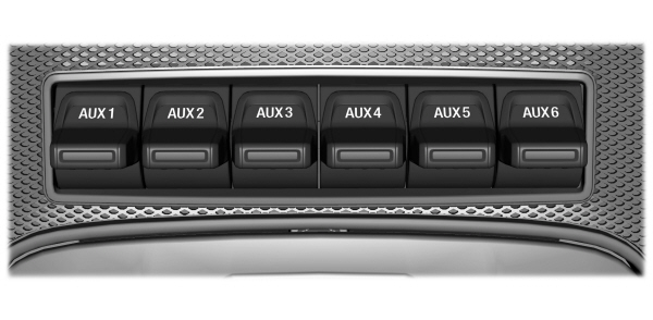
- When adding accessories, equipment, passengers and luggage to your vehicle, do not exceed the total weight capacity of the vehicle or of the front or rear axle (GVWR or GAWR as indicated on the Safety Compliance Certification label).Ask an authorized dealer for specific weight information.
- The Federal Communications Commission (FCC) and Canadian Radio Telecommunications Commission (CRTC) regulate the use of mobile communications systems equipped with radio transmitters, for example, two-way radios, telephones and theft alarms. Any such equipment installed in your vehicle should comply with Federal Communications Commission (FCC) and Canadian Radio Telecommunications Commission (CRTC) regulations, and should be installed by an authorized dealer.
- An authorized dealer needs to install mobile communications systems. Improper installation may harm the operation of your vehicle, particularly if the manufacturer did not design the mobile communication system specifically for automotive use.
- If you or an authorized Ford dealer add any non-Ford electrical or electronic accessories or components to your vehicle, you may adversely affect battery performance and durability.In addition, you may also adversely affect the performance of other electrical systems in the vehicle.
The auxiliary switch option package provides six switches mounted in the overhead console. These switches operate when the vehicle is running or from battery power, depending on the switchable fuse AUXF4's location in the upfitter relay box. We recommend, however, that the engine remain running to maintain battery charge when using the auxiliary switches for extended periods of time or higher current draws.
Note:
When your vehicle has a diesel engine, use the auxiliary switches only when the engine is running. The glow plugs also drain battery power when the ignition key is in the on position. Using the auxiliary switches, even for limited amounts of time, can cause your battery to drain quickly and prevent your vehicle from restarting.
When switched on, the auxiliary switches provide electrical battery power for a variety of personal or commercial uses. Switches 1 through 4 provide 25 amps. Switches 5 and 6 provide 40 amps.
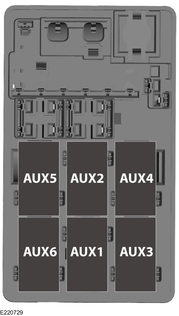
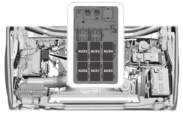
The relay box for the auxiliary switches is in the engine compartment. See your authorized dealer for service.
The relays are coded as shown:
Each switch includes a blunt-cut, sealed wire. The wires are under the instrument panel on the right-hand side of the passenger footwell.
The power leads are coded as shown:
| Switch | Circuit Number | Wire Color | Fuse Amp Rating |
|---|---|---|---|
| AUX 1 | CB117A | Brown with green trace | 25A |
| AUX 2 | CB114A | Violet with orange trace | 25A |
| AUX 3 | CB116A | Blue with green trace | 25A |
| AUX 4 | CB113A | Gray with brown trace | 25A |
| AUX 5 | CB115A | Brown with blue trace | 40A |
| AUX 6 | CB118A | Gray with orange trace | 40A |
Upfitter Interface Module (If Equipped)
The Upfitter Interface Module (UIM) is an electronic control module that operates equipment (such as lift buckets, cranes, motors, salt spreaders and snow plows) with external relays.
If you replace the module, it will require additional programming by the upfitter. Obtain this data directly from the upfitter company. The upfitter contact information is in the vehicle door opening.
For more information on the Upfitter Interface Module and the auxiliary switches, contact your upfitter.
Thank You For Your Feedback