
This view of the Owner's Manual contains the very latest information, which may vary slightly from the printed Owner's Manual originally provided with your vehicle. It may also describe content that is not on or operates differently on your vehicle. Please consider the Owner's Manual originally provided with your vehicle as the primary source of information for your vehicle.

The information contained in this publication was correct at the time of release.In the interest of continuous development, we reserve the right to change specifications, design or equipment at any time without notice or obligation.No part of this publication may be reproduced, transmitted, stored in a retrieval system or translated into any language in any form by any means without our written permission.Errors and omissions excepted.
Copyright © 2024 Ford Motor Company
Fuse Specification Chart


Power Distribution Box
 WARNING:
Always disconnect the battery before servicing high current fuses.
WARNING:
To reduce risk of electrical shock, always replace the cover to the power distribution box before reconnecting the battery or refilling fluid reservoirs.
WARNING:
Always disconnect the battery before servicing high current fuses.
WARNING:
To reduce risk of electrical shock, always replace the cover to the power distribution box before reconnecting the battery or refilling fluid reservoirs. |
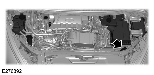
The power distribution box is in the engine compartment. It has high-current fuses that protect your vehicle's main electrical systems from overloads.
If the battery has been disconnected and reconnected, some features need to be reset. See
Changing the 12V Battery
.
| Fuse Location | Fuse Rating | Protected Component |
|---|---|---|
| 1 | 25A3 | Wiper motor. |
| 2 | — | Starter relay. |
| 3 | 15A1 | Rear wiper. Rain sensor |
| 4 | — | Blower motor relay. |
| 5 | 20A3 | Power point 3 - Back of console. |
| 6 | — | Auxiliary heater #2 relay. |
| 7 | 20A1 | Powertrain control module - vehicle power 1. |
| 8 | 20A1 | Powertrain control module - vehicle power 2. |
| 9 | — | Powertrain control module relay. |
| 10 | 20A3 | Power point 1 - driver front. |
| 11 | 15A2 | Powertrain control module - vehicle power 4. |
| 12 | 15A2 | Powertrain control module - vehicle power 3. |
| 13 | 10A2 | Not used (spare). |
| 14 | 10A2 | Not used (spare). |
| 15 | — | Run-start relay. |
| 16 | 20A3 | Power point 2 - console. |
| 17 | 20A3 | Power point 4 - luggage compartment. |
| 18 | 10A1 | Not used (spare). |
| 19 | 10A1 | Run-start electronic power assist steering. |
| 20 | 10A1 | Run/start lighting. |
| 21 | 15A1 | Run/start transmission control. Transmission oil pump start/stop. |
| 22 | 10A1 | Air conditioner clutch solenoid. |
| 23 | 15A1 | Run-start. Blind spot information system. Rear view camera. Adaptive cruise control. Heads-up display. Voltage stability module. |
| 24 | 10A1 | Run-start 7. |
| 25 | 10A2 | Run-start anti-lock brake system. |
| 26 | 10A2 | Run-start powertrain control module. |
| 27 | — | Not used. |
| 28 | 10A1 | Rear washer pump. |
| 29 | — | Not used. |
| 30 | — | Not used. |
| 31 | — | Not used. |
| 32 | — | Electronic fan 1 relay. |
| 33 | — | A/C clutch relay. |
| 34 | 15A1 | Electric steering column lock. |
| 35 | — | Not used. |
| 36 | — | Not used. |
| 37 | — | Not used. |
| 38 | — | Electronic fan 2 relay |
| 39 | — | Electric fan 2 and 3 relay. |
| 40 | — | Headlamp washer relay. |
| 41 | — | Horn relay. |
| 42 | — | Fuel pump relay. |
| 43 | 10A1 | Not used (spare). |
| 44 | 5A1 | Heated washer nozzle. |
| 45 | — | Not used. |
| 46 | 10A2 | Alternator sensor. |
| 47 | 10A2 | Brake on/off switch. |
| 48 | 20A1 | Horn. |
| 49 | 25A1 | Diesel fuel heater. |
| 50 | 10A1 | Power transfer unit fan. |
| 51 | — | Not used. |
| 52 | — | Not used. |
| 53 | 10A1 | Power seats. |
| 54 | 5A2 | Fuel operated heater. |
| 55 | 5A2 | Fuel operated heater. |
1Micro fuse.
2Dual micro fuse.
3M-type fuse.
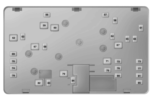
Power Distribution Box - Bottom
There are fuses on the bottom of the fuse box. To access the bottom of the fuse box, do the following:
- Release the two latches, on both sides of the fuse box.
- Raise the inboard side of the fuse box from the cradle.
- Move the fuse box toward the center of the engine compartment.
- Pivot the outboard side of the fuse box to access the bottom side.
| Fuse Location | Fuse Rating | Protected Component |
|---|---|---|
| 56 | 20A1 | Headlamp washer. |
| 57 | 20A1 | Diesel vaporizer. |
| 58 | 30A1 | Fuel pump feed. |
| 59 | 40A2 | 600W Electronic fan 3. |
| 60 | 40A2 | 600W Electronic fan 1. Selective catalytic reductant system. |
| 61 | 40A1 | Left hand side windshield defrost. |
| 62 | 50A2 | Body control module 1. |
| 63 | 25A1 | 600W Electronic fan 2. |
| 64 | 30A1 | Auxiliary heater #3. |
| 65 | 20A1 | Front heated seat. |
| 66 | 40A1 | Right hand side windshield defrost. |
| 67 | 50A2 | Body control module 2. |
| 68 | 40A1 | Heated rear window. |
| 69 | 30A1 | Anti-lock brake system valves. |
| 70 | 30A1 | Passenger seat. |
| 71 | 60A2 | Auxiliary heater #2. |
| 72 | 30A1 | Rear power seats. |
| 73 | 20A1 | Rear heated seats. |
| 74 | 30A1 | Driver seat module. |
| 75 | 30A1 | Auxiliary heater #1. |
| 76 | 20A1 | Transmission oil pump. |
| 77 | 30A1 | Climate control seat module. |
| 78 | 40A1 | Trailer tow module. |
| 79 | 40A1 | Blower motor. |
| 80 | 40A1 | Power liftgate module. |
| 81 | 40A1 | 220 volt inverter. |
| 82 | 60A2 | Anti-lock brake system pump. |
| 83 | 25A1 | Wiper motor #1. |
| 84 | 30A1 | Starter solenoid. |
| 85 | 20A1 | Fuel fire heater. |
| 86 | — | Not used. |
| 87 | 50A2 | Auxiliary blower motor. |
1 M-type fuse.
2J-type fuse.
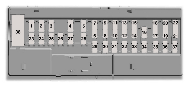
Passenger Compartment Fuse Panel
The fuse panel is under the instrument panel to the left of the steering column.
Note:
It may be easier to access the fuse panel if you remove the finish trim piece.
| Fuse Location | Fuse Rating | Protected Component |
|---|---|---|
| 1 | 10A1 | Not used. |
| 2 | 7.5A1 | Memory seats, lumbar, power mirror. |
| 3 | 20A1 | Driver door unlock. |
| 4 | 5A1 | Aftermarket electronic trailer brake on/off switch. |
| 5 | 20A1 | Ignition switch. Push-button ignition switch. |
| 6 | 10A2 | Heated seat relay coil. |
| 7 | 10A2 | Not used (spare). |
| 8 | 10A2 | Not used (spare). |
| 9 | 10A2 | Not used (spare). |
| 10 | 5A2 | Keypad. Power liftgate module. |
| 11 | 5A2 | Not used. |
| 12 | 7.5A2 | Climate control. Transmission selector. |
| 13 | 7.5A2 | Steering wheel column lock. Cluster. Datalink logic. |
| 14 | 10A2 | Not used. |
| 15 | 10A2 | Datalink gateway module. |
| 16 | 15A1 | Child lock. Liftgate release. |
| 17 | 5A2 | Not used (spare). |
| 18 | 5A2 | Ignition. Push button stop start switch. |
| 19 | 7.5A2 | Passenger airbag disabled indicator. Transmission range indicator. |
| 20 | 7.5A2 | Not used (spare). |
| 21 | 5A2 | Humidity and in-car temperature sensor. Blind spot information system. Rear video camera. Adaptive cruise control. |
| 22 | 5A2 | Occupant classification sensor. |
| 23 | 10A1 | Delayed accessory (power inverter logic, moonroof logic). |
| 24 | 20A1 | Central locking system. |
| 25 | 30A1 | Driver door (window, mirror). |
| 26 | 30A1 | Front passenger door (window, mirror). |
| 27 | 30A1 | Moonroof. |
| 28 | 20A1 | Amplifier. |
| 29 | 30A1 | Rear driver side door (window). |
| 30 | 30A1 | Rear passenger side door (window). |
| 31 | 15A1 | Not used (spare). |
| 32 | 10A1 | Global positioning system. Display. Voice control. Adaptive cruise control. Radio. |
| 33 | 20A1 | Radio. |
| 34 | 30A1 | Run-start bus (fuse 19, 20, 21, 22, 35, 36, 37, circuit breaker). |
| 35 | 5A1 | Restraints control module. |
| 36 | 15A1 | Auto-dimming rear view mirror. Heated seat. All-wheel drive. |
| 37 | 20A1 | Voltage stability module logic power. |
| 38 | 30A | Not used (spare). |
1Micro fuse.
2Dual micro fuse.
Fuse on Battery
The fuse is on the positive (+) terminal connector to the battery.
| Fuse Rating | Protected Component |
|---|---|
| 40 A | Selective catalytic reductant system - 2.0L EcoBlue (88kW/120PS) (YN)/2.0L EcoBlue (110kW/150PS) (YM)/2.0L EcoBlue (147kW/190PS) (BC). |
| 60 A | Cooling fan - 2.0L EcoBlue (177kW/240PS) (YL). |
Reductant Dosage Control Module Fuse Box
| Protected Component |
|---|
| Reductant dosage control module. |