About Us - Raptor
Contacting Us
Introduction
Symbols Glossary
Data Privacy
At a Glance - Raptor
Visual Search
- Steering Wheel - Excluding: Raptor
- Steering Wheel - Raptor
- Steering Wheel - Police
- Instrument Panel - Excluding: Raptor/Police
- Instrument Panel - Raptor
- Instrument Panel - Police Responder
- Vehicle Interior - Excluding: Raptor/Police
- Vehicle Interior - Raptor
- Vehicle Interior
- Front Exterior - Excluding: Raptor/Police
- Front Exterior - Raptor
- Front Exterior - Police
- Rear Exterior - Excluding: Raptor/Police
- Rear Exterior - Raptor
- Rear Exterior - Police
Child Safety
- Child Safety Precautions
- Booster Seats
- Child Safety Locks (If Equipped)
Child Restraint Anchor Points
Child Restraints
Installing Child Restraints
Seatbelts
- Seatbelt Precautions
- Fastening and Unfastening the Seatbelts
- Adjusting the Seatbelts During Pregnancy
- Adjusting the Seatbelt Height
- Adjusting the Seatbelt Length
- Checking the Seatbelts
- Seatbelt Extensions
Sensitive Locking Mode
Automatic Locking Mode
Seatbelt Reminder
Personal Safety System™
Airbags
- How Do the Front Airbags Work
- How Do the Side Airbags Work
- How Do the Knee Airbags Work
- How Does the Safety Canopy™ Work
- Airbag Precautions
- Properly Adjusting the Driver and Front Passenger Seats
- Children and Airbags
- Crash Sensors and Airbag Indicator
- Crash Sensors and Airbag Indicator - Police Responder
- Disposing of Airbags
Front Passenger Sensing System
Pedestrian Alert System (If Equipped)
911 Assist (If Equipped)
Keys and Remote Controls
- Remote Control Limitations
- Using the Remote Control - Police Responder
- Using the Remote Control
- Opening and Closing the Flip Key
- Removing the Key Blade
- Sounding the Panic Alarm
- Locating Your Vehicle
- Changing the Remote Control Battery - Police Responder
- Changing the Remote Control Battery - Vehicles With: Push Button Start
- Changing the Remote Control Battery - Vehicles With: Flip Key
- Replacing a Lost Key or Remote Control
- Programming the Remote Control - Vehicles With: Push Button Start
- Programming the Remote Control - Vehicles With: Flip Key
Keys and Remote Controls – Troubleshooting
MyKey™ (If Equipped)
Doors and Locks
- Doors and Locks Audible Warnings
Operating the Doors From Outside Your Vehicle
Operating the Doors From Inside Your Vehicle
Autounlock (If Equipped)
Autolock (If Equipped)
Mislock (If Equipped)
Doors and Locks – Troubleshooting
Keyless Entry (If Equipped)
- Keyless Entry Limitations
- Keyless Entry Settings
- Using Keyless Entry
Keyless Entry – Troubleshooting
Keyless Entry Keypad (If Equipped)
- What Is the Keyless Entry Keypad
- Keyless Entry Keypad Limitations
- Locating the Keyless Entry Keypad
- Keyless Entry Keypad Master Access Code - Vehicles With: Flip Key
- Keyless Entry Keypad Master Access Code - Vehicles With: Push Button Start
- Keyless Entry Keypad Personal Access Codes
- Using the Keyless Entry Keypad
Keyless Entry Keypad – Troubleshooting
Easy Entry and Exit (If Equipped)
Tailgate - Vehicles With: Manual Tailgate
- Tailgate Precautions
- Locking and Unlocking the Tailgate
- Removing and Installing the Tailgate
- Tailgate Work Surface (If Equipped)
Opening the Tailgate
Tailgate Step (If Equipped)
Bed Extender (If Equipped)
Tailgate - Vehicles With: Power Tailgate
- Tailgate Precautions
- Removing and Installing the Tailgate
- Tailgate Work Surface (If Equipped)
Opening the Tailgate
Closing the Tailgate
Tailgate Step (If Equipped)
Bed Extender (If Equipped)
Tailgate – Troubleshooting
Tailgate - Vehicles With: Remote Release Tailgate
- Tailgate Precautions
- Removing and Installing the Tailgate
- Tailgate Work Surface (If Equipped)
Opening the Tailgate
Tailgate Step (If Equipped)
Bed Extender (If Equipped)
Tailgate – Troubleshooting
Security
Passive Anti-Theft System
Anti-Theft Alarm System (If Equipped)
Anti-Theft Alarm System Settings (If Equipped)
Security – Troubleshooting
Power Running Boards (If Equipped)
Steering Wheel
- Adjusting the Steering Wheel - Vehicles With: Manual Adjustable Steering Column
- Adjusting the Steering Wheel - Vehicles With: Power Adjustable Steering Column
- Resetting the Stopping Position - Vehicles With: Power Adjustable Steering Column
- Horn
- Switching the Heated Steering Wheel On and Off - Vehicles With: Heated Steering Wheel
Adjustable Pedals (If Equipped)
Wipers and Washers
- Checking the Wiper Blades
- Replacing the Front Wiper Blades
- Wipers and Washers Videos
Autowipers (If Equipped)
Washers
Wipers and Washers – Troubleshooting
Exterior Lighting
- Exterior Lighting Control
- Exterior Lighting Control
- Using the Turn Signal Lamps
- How Do Cornering Lamps Work (If Equipped)
- Switching the Daytime Running Lamps On and Off - Vehicles With: Configurable Daytime Running Lamps
- Switching the Daytime Running Lamps On and Off - Vehicles With: Daytime Running Lamps (DRL)
- Using the Front Fog Lamps (If Equipped)
- Switching the Cargo Lamps On
- Switching the Spot Lamps On and Off (If Equipped)
- Using the Off-Road Driving Lamps (If Equipped)
- Exterior Lamps On Audible Warning
- Exterior Lighting Videos
Headlamps – Troubleshooting
Autolamps
Exterior Lamps
Exterior Zone Lighting (If Equipped)
Automatic High Beam Control
Automatic High Beam Control – Troubleshooting
Glare Free Lighting (If Equipped)
Glare Free Lighting – Troubleshooting (If Equipped)
Adaptive Front Lighting (If Equipped)
Interior Lighting
- Switching All of the Interior Lamps On and Off
- Switching the Front Interior Lamps On and Off
- Switching the Front Interior Lamps On and Off - Police Responder
- Switching the Rear Interior Lamps On and Off
- Adjusting the Instrument Panel Lighting Brightness
Interior Lamp Function
Ambient Lighting
Interior Lighting – Troubleshooting
Windows
Interior Mirror
- Interior Mirror Precautions
- Manually Dimming the Interior Mirror
Auto-Dimming Interior Mirror (If Equipped)
Exterior Mirrors
Moonroof (If Equipped)
Instrument Cluster
- Instrument Cluster Overview - Vehicles With: 4.2 Inch Screen
- Instrument Cluster Overview - Vehicles With: 8 Inch Screen
- Instrument Cluster Overview - Vehicles With: 12 Inch Screen
- Tachometer
- Speedometer
- Engine Coolant Temperature Gauge
- Engine Oil Pressure Gauge
- Transmission Fluid Temperature Gauge
- Turbo Boost Gauge (If Equipped)
- What Are the Instrument Cluster Warning Lamps
- Instrument Cluster Warning Lamps
- What Are the Instrument Cluster Indicators
- Instrument Cluster Indicators
Fuel Gauge
Instrument Cluster Display
- Using the Instrument Cluster Display Controls
- Instrument Cluster Display Main Menu - Vehicles With: 12 Inch Screen
- Instrument Cluster Display Main Menu - Raptor
- Instrument Cluster Display Main Menu - Vehicles With: 4.2 Inch Screen
- Instrument Cluster Display Main Menu - Vehicles With: 8 Inch Screen
- Customizing the Instrument Cluster Display
- Brake Coach
- Trip Summary
Trip Computer - Vehicles With: 4.2 Inch Screen
Trip Computer - Vehicles With: 8 Inch Screen/12 Inch Screen
Personalized Settings
Hybrid Display Information
Remote Start (If Equipped)
Climate Control - Vehicles With: Automatic Temperature Control
- Identifying the Climate Control Unit
- Switching Climate Control On and Off
- Switching Recirculated Air On and Off
- Switching Air Conditioning On and Off
- Switching Defrost On and Off
- Switching Maximum Defrost On and Off
- Switching Maximum Cooling On and Off
- Switching the Heated Wiper Park On and Off (If Equipped)
- Switching the Heated Rear Window On and Off
- Setting the Blower Motor Speed
- Switching the Heated Mirrors On and Off
- Setting the Temperature
- Directing the Flow of Air
- Climate Control Hints
Climate Control - Vehicles With: Manual Temperature Control
- Identifying the Climate Control Unit
- Switching Climate Control On and Off
- Switching Recirculated Air On and Off
- Switching Air Conditioning On and Off
- Switching Defrost On and Off
- Switching Maximum Defrost On and Off
- Switching Maximum Cooling On and Off
- Switching the Heated Rear Window On and Off
- Setting the Blower Motor Speed
- Switching the Heated Mirrors On and Off
- Setting the Temperature
- Directing the Flow of Air
- Climate Control Hints
Interior Air Quality
Front Seats
- Front Seat Precautions
- Sitting in the Correct Position
Manual Seats (If Equipped)
Power Seats (If Equipped)
Massage Seats (If Equipped)
Heated Seats (If Equipped)
Ventilated Seats (If Equipped)
Rear Seats (If Equipped)
Rear Occupant Alert System (If Equipped)
Memory Function (If Equipped)
Garage Door Opener (If Equipped)
USB Ports
Power Outlet - Vehicles With: Pickup Bed Power Generator Outlet
- What Is the Power Outlet
- Power Outlet Precautions - Vehicles With: 2kW
- Power Outlet Precautions - Vehicles With: 2.4kW/7.2kW
- Locating the Power Outlets
- Power Outlet Indicators - Vehicles With: 2kW
- Power Outlet Indicators - Vehicles With: 2.4kW/7.2kW
- What Is Utility Idle Mode - Vehicles With: Flip Key
- Switching Utility Idle On and Off - Vehicles With: Flip Key
- What Is Generator Mode
- Switching Generator Mode On and Off
- Resetting Ground Fault Detection
- Resetting the Circuit Breaker - Vehicles With: 7.2kW
- Power Outlet Videos
Power Outlet – Troubleshooting
Power Outlet - Vehicles With: 120V Power Outlet
Power Outlet - Vehicles With: 12V Power Outlet
Center Console Work Surface
- Using the Center Console Work Surface - Vehicles With: Column Shift
- Using the Center Console Work Surface - Vehicles With: Console Shift
Center Console Work Surface – Troubleshooting
Wireless Accessory Charger (If Equipped)
Storage
Cup Holders
Glove Compartment
Under Seat Storage
Glasses Holder
Starting and Stopping the Engine
- Starting and Stopping the Engine – Precautions
- Ignition Switch (If Equipped)
- Push Button Ignition Switch (If Equipped)
- Starting a Gasoline Engine - Vehicles Without: Push Button Start
- Starting a Gasoline Engine - Vehicles With: Push Button Start
- Starting a Hybrid Electric Vehicle System - Vehicles Without: Push Button Start
- Starting a Hybrid Electric Vehicle System - Vehicles With: Push Button Start
- Restarting the Engine After Stopping It - Vehicles With: Push Button Start
- Stopping the Engine When Your Vehicle is Stationary - Vehicles Without: Push Button Start
- Stopping the Engine When Your Vehicle is Stationary - Vehicles With: Push Button Start
- Stopping the Engine When Your Vehicle is Moving - Vehicles Without: Push Button Start
- Stopping the Engine When Your Vehicle is Moving - Vehicles With: Push Button Start
- Accessing the Passive Key Backup Position
- Starting and Stopping the Engine – Warning Lamps
- Starting and Stopping the Engine – Information Messages
- Starting and Stopping the Engine – Frequently Asked Questions - Gasoline, Vehicles Without: Push Button Start
- Starting and Stopping the Engine – Frequently Asked Questions - Gasoline, Vehicles With: Push Button Start
Starting the Engine
Engine Block Heater (If Equipped)
Stopping the Engine
Automatic Engine Stop - Vehicles With: Keyless Entry and Push Button Start
Starting and Stopping the Engine – Troubleshooting
Hybrid Electric Vehicle Information (If Equipped)
- What is a Hybrid Electric Vehicle
- How Does a Hybrid Electric Vehicle Work
- Hybrid Electric Vehicle Driving Characteristics
- Hybrid Electric Vehicle Indicators
Hybrid Electric Vehicle Information – Troubleshooting
Eco Idle – Troubleshooting
Auto-Start-Stop (If Equipped)
Fuel and Refueling
- Fuel and Refueling Precautions
- Locating the Fuel Filler Funnel
- Fuel Tank Capacity - Excluding: Hybrid Electric Vehicle (HEV)
- Fuel Tank Capacity - Hybrid Electric Vehicle (HEV)
Fuel Quality
Running Out of Fuel
Refueling
Fuel and Refueling – Troubleshooting
Catalytic Converter
- What Is the Catalytic Converter
- Catalytic Converter Precautions
Catalytic Converter – Troubleshooting
High Voltage Battery - Hybrid Electric Vehicle (HEV)
Automatic Transmission
- Automatic Transmission Precautions
- Shifting Your Vehicle Into Gear
- Shifting Your Vehicle Into Gear - Raptor
- Shifting Your Vehicle Into Gear - Police Responder
- Automatic Transmission Audible Warnings
- Using Progressive Range Selection
- Stowing the Selector Lever
- Stowing the Selector Lever - Raptor
Automatic Transmission Positions
Manually Shifting Gears
Temporary Neutral Mode
Automatic Return to Park (P)
Manual Park Release
Four-Wheel Drive (If Equipped)
- How Does Four-Wheel Drive Work
- How Does Four-Wheel Drive Work - Raptor
- Four-Wheel Drive Precautions
- Four-Wheel Drive Limitations
- Selecting a Four-Wheel Drive Mode
- Selecting a Four-Wheel Drive Mode - Raptor
- Four-Wheel Drive Indicators
Four-Wheel Drive Modes
Four-Wheel Drive – Troubleshooting
Electronic Locking Differential (If Equipped)
- What Is the Electronic Locking Differential
- How Does the Electronic Locking Differential Work
- How Does the Electronic Locking Differential Work - Raptor
- Electronic Locking Differential Precautions
- Switching the Electronic Locking Differential On and Off - 4x4
- Switching the Electronic Locking Differential On and Off - Raptor
- Switching the Electronic Locking Differential On and Off - 4x2
- Electronic Locking Differential Indicators
Electronic Locking Differential – Troubleshooting
Brakes
- Brake Precautions
- Brake Over Accelerator
- Brake Over Accelerator - Raptor
- Locating the Brake Fluid Reservoir
- Checking the Brake Fluid
- Brake Fluid Specification
Anti-Lock Braking System
Brakes – Troubleshooting
Electric Parking Brake
- What Is the Electric Parking Brake
- Applying the Electric Parking Brake
- Applying the Electric Parking Brake in an Emergency
- Manually Releasing the Electric Parking Brake
- Automatically Releasing the Electric Parking Brake
- Electric Parking Brake Audible Warning
- Releasing the Electric Parking Brake if the Vehicle Battery Has Run Out of Charge
Electric Parking Brake – Troubleshooting
Reverse Brake Assist (If Equipped)
Hill Start Assist
- What Is Hill Start Assist
- How Does Hill Start Assist Work
- Hill Start Assist Precautions
Hill Start Assist – Troubleshooting
Auto Hold
Traction Control
- What Is Traction Control
- How Does Traction Control Work
- Switching Traction Control On and Off
- Traction Control Indicator
Traction Control – Troubleshooting
Stability Control
Trail Control
- What Is Trail Control
- Trail Control Limitations
- Switching Trail Control On and Off
- Setting the Trail Control Speed
- Canceling the Set Speed
- Trail Control Indicators
Trail One Pedal Drive
Trail One Pedal Drive – Troubleshooting
Trail Control – Troubleshooting
Trail Turn Assist (If Equipped)
Hill Descent Control (If Equipped)
Steering
- Steering Videos
Electric Power Steering
Steering – Troubleshooting
Parking Aids (If Equipped)
- Parking Aid Precautions
- Switching Parking Aid On and Off
- Parking Aid Indicators
- Parking Aids Videos
Rear Parking Aid
Front Parking Aid
Side Parking Aid
Parking Aids – Troubleshooting
Rear View Camera
360 Degree Camera (If Equipped)
Active Park Assist (If Equipped)
Cruise Control (If Equipped)
Adaptive Cruise Control (If Equipped)
- How Does Adaptive Cruise Control With Stop and Go Work
- Adaptive Cruise Control Precautions
- Adaptive Cruise Control Limitations
- Switching Adaptive Cruise Control On and Off
- Adaptive Cruise Control Automatic Cancellation
- Setting the Adaptive Cruise Control Speed
- Setting the Adaptive Cruise Control Gap
- Canceling the Set Speed
- Resuming the Set Speed
- Overriding the Set Speed
- Adaptive Cruise Control Indicators
- Switching From Adaptive Cruise Control to Cruise Control
- How Does Intelligent Adaptive Cruise Control Work
- Intelligent Adaptive Cruise Control Precautions
- Intelligent Adaptive Cruise Control Requirements
- Intelligent Adaptive Cruise Control Limitations
- Switching Intelligent Mode On and Off
- Adjusting the Set Speed Tolerance
- Intelligent Adaptive Cruise Control Alerts
- Intelligent Adaptive Cruise Control Indicators
Lane Centering
Intelligent Adaptive Cruise Control
Adaptive Cruise Control – Troubleshooting
BlueCruise (If Equipped)
Drive Mode Control
- What Is Drive Mode Control
- How Does Drive Mode Control Work
- Selecting a Drive Mode
- Selecting a Drive Mode - Raptor
- Baja - Raptor
- Deep Snow/Sand - 4x4
- Eco - 4x4
- Eco - 4x2
- Mud/Ruts - 4x4
- Normal - Raptor
- Normal - 4x4
- Normal - 4x2
- Off-Road
- Rock Crawl - 4x4
- Rock Crawl - Raptor
- Slippery - 4x4, Vehicles With: 2-Speed Torque On Demand
- Slippery - Raptor
- Slippery - 4x4, Vehicles With: Electronic Shift-On-The-Fly
- Slippery - 4x2
- Sport - 4x4, Vehicles With: 2-Speed Torque On Demand
- Sport - Raptor
- Sport - 4x4, Vehicles With: Electronic Shift-On-The-Fly
- Sport - 4x2
- Tow/Haul - 4x4
- Tow/Haul - Raptor
- Tow/Haul - 4x2
- Trail - 4x2
Drive Modes
Drive Mode Control – Troubleshooting
Lane Keeping System (If Equipped)
- What Is the Lane Keeping System
- How Does the Lane Keeping System Work
- Lane Keeping System Precautions
- Lane Keeping System Limitations
- Switching the Lane Keeping System On and Off
- Switching the Lane Keeping System Mode
- Lane Keeping System Indicators
Alert Mode
Aid Mode
Alert and Aid Mode
Lane Keeping System – Troubleshooting
Blind Spot Information System (If Equipped)
- What Is Blind Spot Information System
- How Does Blind Spot Information System Work
- Blind Spot Information System Precautions
- Blind Spot Information System Limitations
- Blind Spot Information System Requirements
- Switching Blind Spot Information System On and Off
- Locating the Blind Spot Information System Sensors
- Blind Spot Information System Indicators
Blind Spot Information System With Trailer Coverage (If Equipped)
Blind Spot Information System – Troubleshooting
Cross Traffic Alert (If Equipped)
Pre-Collision Assist (If Equipped)
- What Is Pre-Collision Assist
- How Does Pre-Collision Assist Work
- Pre-Collision Assist Precautions
- Pre-Collision Assist Limitations
- Switching Pre-Collision Assist On and Off - Police Responder
- Switching Pre-Collision Assist On and Off (If Equipped)
- Locating the Pre-Collision Assist Sensors - Police Responder
- Locating the Pre-Collision Assist Sensors
- Pre-Collision Assist – Warning Lamps
- Pre-Collision Assist – Information Messages - Police Responder
- Pre-Collision Assist – Information Messages
- Pre-Collision Assist – Frequently Asked Questions - Police Responder
- Pre-Collision Assist – Frequently Asked Questions - Vehicles With: Intersection Assist
- Pre-Collision Assist – Frequently Asked Questions
Distance Indication
Automatic Emergency Braking
Evasive Steering Assist
Pre-Collision Assist – Troubleshooting
Driver Alert (If Equipped)
Load Carrying
Pickup Bed
- Pickup Bed Precautions
Pickup Bed Anchor Points
Tailgate Anchor Points
Connecting a Trailer
- Connecting a Trailer Precautions
- Connecting a Trailer
- Trailer Lighting Check
Connecting a Trailer – Troubleshooting
Towing a Trailer
- Towing a Trailer Precautions
- Trailer Brake Precautions
- Towing a Trailer Limitations
- Loading Your Trailer
- Trailer Towing Hints
- Launching or Retrieving a Boat or Personal Watercraft
Towing Weights and Dimensions
Towing a Trailer – Troubleshooting
Integrated Trailer Brake Controller (If Equipped)
- What Is the Integrated Trailer Brake Controller
- Integrated Trailer Brake Controller Precautions
- Using the Integrated Trailer Brake Controller
- Adjusting the Integrated Trailer Brake Controller Mode
Integrated Trailer Brake Controller – Troubleshooting
Trailer Sway Control
Trailer Hitching Assistance (If Equipped)
Smart Hitch (If Equipped)
Onboard Scales (If Equipped)
Trailer Backup Assistance (If Equipped)
- What is Trailer Backup Assistance
- How Does Trailer Backup Assistance Work
- Trailer Backup Assistance Precautions
- Switching Trailer Backup Assistance On and Off
- Using the Trailer Backup Assistance Controller
- Using the Trailer Backup Assistance Views
Setting Up the Trailer Backup Assistance for a Conventional Trailer
Trailer Backup Assistance – Troubleshooting
Trailer Reverse Guidance (If Equipped)
- What Is Trailer Reverse Guidance
- How Does Trailer Reverse Guidance Work
- Trailer Reverse Guidance Precautions
- Switching Trailer Reverse Guidance On and Off
- Using Trailer Reverse Guidance Views
- Trailer Reverse Guidance Videos
Setting Up Trailer Reverse Guidance for a Conventional Trailer
Trailer Reverse Guidance – Troubleshooting
Driving Hints
- What Is Off-Road Driving
- Off-Road Driving Precautions - Raptor
- Basic Off-Road Driving Techniques
- Basic Off-Road Driving Techniques - Raptor
- Driving Off-Road - Raptor
- Driving Your Vehicle at High Speeds - Raptor
- Driving Through Water Limitations - Raptor
- Water Wading
- Off-Road Driving Aids - Raptor
- After Driving Your Vehicle Off-Road
- After Driving Your Vehicle Off-Road - Raptor
- Cold Weather Precautions
- Driving on Snow and Ice
- Breaking-In
- Driving Economically
- Floor Mats
Off-Road Driving
Driving in Special Conditions
Snow Plowing - Vehicles Without: Snow Plow Mode
Snow Plowing - Vehicles With: Snow Plow Mode
Crash and Breakdown Information
- Roadside Assistance
- High Voltage Battery Vehicle Precautions - Hybrid Electric Vehicle (HEV)
- Switching the Hazard Flashers On and Off
- Post-Collision Braking
- Transporting the Vehicle
Jump Starting the Vehicle
Post-Crash Alert System
Automatic Crash Shutoff
Recovery Towing
Towing Your Vehicle
Fuses
- Fuse Precautions
- Identifying Fuse Types
Under Hood Fuse Box
Body Control Module Fuse Box
Fuses – Troubleshooting
Maintenance
- Maintenance Precautions
- Opening and Closing the Hood
- Under Hood Overview - 2.7L EcoBoost™
- Under Hood Overview - 3.3L
- Under Hood Overview - 3.5L Ecoboost™
- Under Hood Overview - 3.5L, Hybrid Electric Vehicle (HEV)
- Under Hood Overview - 5.0L
- Checking the Coolant
- Changing the Fuel Filter - Gasoline
- Changing the 12V Battery
- Adjusting the Headlamps - Vehicles With: LED Headlamps
- Adjusting the Headlamps - Vehicles With: Halogen Headlamps
- Exterior Bulb Specification Chart
- Removing a Rear Lamp Assembly
- Changing a Headlamp Bulb
- Changing a Front Turn Signal Lamp Bulb
- Changing a Front Side Marker Lamp Bulb
- Changing a Front Fog Lamp Bulb (If Equipped)
- Changing a Rear Lamp Bulb
- Changing a Stoplamp Bulb
- Changing a Rear Turn Signal Lamp Bulb
- Changing a Reversing Lamp Bulb
- Changing a High Mounted Stoplamp Bulb
- Changing a License Plate Lamp Bulb
- Drive Belt Routing - 2.7L EcoBoost™, Vehicles With: Dual Generators
- Drive Belt Routing - 2.7L EcoBoost™, Vehicles With: Single Generator
- Drive Belt Routing - 3.3L
- Drive Belt Routing - 3.5L Ecoboost™, Vehicles With: Dual Generators
- Drive Belt Routing - 3.5L Ecoboost™, Vehicles With: Single Generator
- Drive Belt Routing - 3.5L, Hybrid Electric Vehicle (HEV)
- Drive Belt Routing - 5.0L, Vehicles With: Dual Generators
- Drive Belt Routing - 5.0L, Vehicles With: Single Generator
Engine Oil
Engine Air Filter
Exterior Bulbs
Interior Bulbs
Vehicle Care
- Cleaning Products
- Cleaning the Exterior Precautions
- Cleaning the Exterior Precautions - Raptor
- Cleaning Headlamps and Rear Lamps
- Cleaning Windows and Wiper Blades
- Cleaning Chrome, Aluminium or Stainless Steel
- Cleaning Wheels
- Cleaning the Engine Compartment
- Cleaning Stripes or Graphics
- Cleaning Camera Lenses and Sensors
- Cleaning the Underbody
- Repairing Minor Paint Damage
- Waxing Your Vehicle
Cleaning the Exterior
Cleaning the Interior
Storing Your Vehicle
Wheel and Tire Information
Tire Care
Tire Pressure Monitoring System
Changing a Road Wheel
Capacities and Specifications
- Engine Specifications - 2.7L EcoBoost™
- Engine Specifications - 3.3L
- Engine Specifications - 3.5L Ecoboost™
- Engine Specifications - 3.5L, Hybrid Electric Vehicle (HEV)
- Engine Specifications - 5.0L
- Motorcraft Parts - 2.7L EcoBoost™
- Motorcraft Parts - 3.3L
- Motorcraft Parts - 3.5L Ecoboost™
- Motorcraft Parts - Raptor
- Motorcraft Parts - 3.5L, Hybrid Electric Vehicle (HEV)
- Motorcraft Parts - 5.0L
- Engine Oil Capacity and Specification - 2.7L EcoBoost™
- Engine Oil Capacity and Specification - 3.3L
- Engine Oil Capacity and Specification - 3.5L Ecoboost™
- Engine Oil Capacity and Specification - 3.5L, Hybrid Electric Vehicle (HEV)
- Engine Oil Capacity and Specification - 5.0L
- Cooling System Capacity and Specification - 2.7L EcoBoost™
- Cooling System Capacity and Specification - 3.3L
- Cooling System Capacity and Specification - 3.5L Ecoboost™
- Cooling System Capacity and Specification - Raptor
- Cooling System Capacity and Specification - 3.5L, Hybrid Electric Vehicle (HEV)
- Cooling System Capacity and Specification - 5.0L
- Fuel Tank Capacity - Gasoline, Excluding: Hybrid Electric Vehicle (HEV)
- Fuel Tank Capacity - Raptor
- Fuel Tank Capacity - Gasoline, Hybrid Electric Vehicle (HEV)
- Air Conditioning System Capacity and Specification - 2.7L EcoBoost™
- Air Conditioning System Capacity and Specification - 3.3L
- Air Conditioning System Capacity and Specification - 3.5L Ecoboost™
- Air Conditioning System Capacity and Specification - 3.5L, Hybrid Electric Vehicle (HEV)
- Air Conditioning System Capacity and Specification - 5.0L
- Washer Fluid Specification
- Brake Fluid Specification
- Transfer Case Fluid Capacity and Specification
- Transfer Case Fluid Capacity and Specification - Raptor
- Front Axle Fluid Capacity and Specification
- Rear Axle Fluid Capacity and Specification
- Rear Axle Fluid Capacity and Specification - Raptor
- Rear Axle Fluid Capacity and Specification - Police Responder
Vehicle Identification
Vehicle Identification Number
Connected Vehicle
- What Is a Connected Vehicle
- Connected Vehicle Requirements
- Connected Vehicle Limitations
- Connecting the Vehicle to a Wi-Fi Network
- Connected Vehicle Settings
Connecting the Vehicle to a Mobile Network
Connected Vehicle – Troubleshooting
Vehicle Wi-Fi Hotspot
Audio System
- Audio System Precautions
- Identifying the Audio Unit
- Switching the Audio Unit On and Off
- Selecting the Audio Source
- Playing or Pausing the Audio Source
- Adjusting the Volume
- Switching Shuffle Mode On and Off
- Switching Repeat Mode On and Off
- Setting a Memory Preset
- Muting the Audio
- Adjusting the Sound Settings
- Setting the Clock and Date
- Switching the Display On and Off
AM/FM Radio
Digital Radio (If Equipped)
Satellite Radio (If Equipped)
Audio System – Troubleshooting
Center Display
Voice Interaction
Alexa Built-In
Phone
Apps
Personal Profiles (If Equipped)
Navigation (If Equipped)
- Connected Navigation
- Accessing Navigation
- Navigation Map Updates
- Trailer Towing Navigation
Adjusting the Map
Live Traffic
Setting a Destination
Waypoints
Route Guidance
Driver Identification (If Equipped)
- How Does Driver Identification Work
- Signing In as a Driver
Driver Identification – Troubleshooting
Vehicle Software Updates
Vehicle System Reset
Accessories
Auxiliary Switches
Warranty Terms and Conditions - Raptor
Ford Protect
Scheduled Maintenance
Customer Information
- Rollover Warning
- The Better Business Bureau Auto Line Program
- The Mediation and Arbitration Program
- Ordering a Canadian French Owner's Manual
- Reporting Safety Defects in the United States
- Reporting Safety Defects in Canada
- Blind Spot Information System Sensors
- Body Control Module
- Cruise Control Module
- Keys and Remote Controls
- Passive Anti-Theft System
- Radio Transceiver Module
- SYNC
- Telematics Control Unit
- Tire Pressure Monitoring System Sensors - Vehicles With: 315 MHz Sensors
- Tire Pressure Monitoring System Sensors - Vehicles With: 433 MHz Sensors
- Wireless Accessory Charging Module
- Perchlorate
- Replacement Parts Recommendation
- Mobile Communications Equipment
- End User License Agreement
- Emission Law
- Export Unique Options
- Warranty Information
Radio Frequency Certification Labels
Decommissioning the Vehicle
Appendices

This view of the Owner's Manual contains the very latest information, which may vary slightly from the printed Owner's Manual originally provided with your vehicle. It may also describe content that is not on or operates differently on your vehicle. Please consider the Owner's Manual originally provided with your vehicle as the primary source of information for your vehicle.
The information contained in this publication was correct at the time of release.In the interest of continuous development, we reserve the right to change specifications, design or equipment at any time without notice or obligation.No part of this publication may be reproduced, transmitted, stored in a retrieval system or translated into any language in any form by any means without our written permission.Errors and omissions excepted.
Copyright © 2024 Ford Motor Company
Crash Sensors and Airbag Indicator - Police Responder


 WARNING:
Modifying or adding equipment to the front of your vehicle could affect the performance of the airbag system, increasing the risk of injury. This includes the hood, bumper system, frame, front body structure, tow hooks, hood pins, push bar and snowplows.
WARNING:
Modifying or adding equipment to the front of your vehicle could affect the performance of the airbag system, increasing the risk of injury. This includes the hood, bumper system, frame, front body structure, tow hooks, hood pins, push bar and snowplows. |
Your vehicle has a collection of crash and occupant sensors. These sensors provide information to the restraints control module which activates the following:
- Front seatbelt pretensioners.
- Driver airbag.
- Passenger airbag.
- Knee airbag(s).
- Seat mounted side airbags.
- Safety Canopy.
Based on the type of crash, the restraints control module deploys the appropriate safety devices.
The restraints control module also monitors the readiness of the above safety devices plus the crash and occupant sensors. The readiness of the safety system is indicated by a warning indicator light in the instrument cluster or by a backup tone if the warning light is not working. Routine maintenance of the airbag is not required.
A difficulty with the system is indicated by one or more of the following:
- The readiness light either flashes or stays on.
- You hear a series of five tones. The tone pattern repeats periodically until the problem, the light or both are repaired.
- The readiness light will not illuminate immediately after you switch the ignition on.
If any of these things happen, even intermittently, have the supplemental restraint system serviced immediately. Unless serviced, the system may not function properly in the event of a crash.
The fact that the seatbelt pretensioners or airbags did not activate for both front seat occupants in a crash does not mean that something is wrong with the system. Rather, it means the restraints control module determined the accident conditions (crash severity, belt usage) were not appropriate to activate these safety devices.- The front airbags activate only in frontal and near-frontal crashes, not rollovers, side impacts or rear impacts, unless the crash causes sufficient frontal deceleration.
- The seatbelt pretensioners activate in frontal, near-frontal and side crashes and in rollovers.
- The side airbags inflate in certain side impact crashes and in rollovers. Side airbags may activate in other types of crashes if the vehicle experiences sufficient sideways motion or deformation.
- The knee airbag(s) may deploy based on crash severity and occupant conditions.
- The Safety Canopy inflates in certain side impact crashes or rollover events. The Safety Canopy may activate in other types of crashes if the vehicle experiences sufficient sideways motion or deformation, or a certain likelihood of rollover.
Airbags and Police Equipment
|
WARNING:
Do not place objects or mount equipment on or near the airbag cover, on the side of the front or rear seatbacks, or in areas that may come into contact with a deploying airbag. Failure to follow these instructions may increase the risk of personal injury in the event of a crash.
WARNING:
Keep the areas in front of the airbags free from obstruction. Do not affix anything to or over the airbag covers. Objects could become projectiles during airbag deployment. Failure to follow this instruction could result in personal injury or death. |
Dual driver and passenger airbags, side airbags and knee airbags affect the way police equipment can be mounted in police vehicles.
Any surfaces that could come into contact with an airbag, once it has deployed, must not damage the airbag or alter its deployment path.
Once the airbag has fully deployed, any peripheral equipment surfaces that could come into contact with the airbag, such as when the airbag deflates with the loading of an occupant, must not damage the airbag or alter its deployment path. Sharp edges, corners or protrusions could damage the nylon airbag material and reduce the effectiveness of the airbag.
Some approximate dimensions for airbags, at full inflation, are provided. These dimensions are somewhat flexible and represent free form deployments without the loading of occupants. The shaded areas in Figures 8 through 10 represent available police equipment mounting zones. These zones are shown for police vehicles with standard bucket seats. The zone dimensions provided in Figures 8 through 10 are approximate and will vary with the loading of occupants in the seats.
All airbag and equipment mounting zone dimensions are approximate due to different airbag deployment characteristics.
Do not mount equipment between the side of the front seat and the door trim that will block deployment of the side airbag.
Do not mount equipment between the seats and the body side as shown in Figure 7 that would prevent the side curtain airbag from achieving occupant coverage.
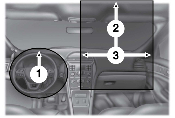
Figure 1 - Driver and Passenger Airbag Dimensions
| 1. 2. 3. |
Note:
Do not place objects between the airbags due to airbag variability.
Figure 2 - Side View of the Driver Airbag at Full Inflation
| 1. |
Figure 3 - Top View of the Driver and Passenger Airbags at Full Inflation
| 1. 2. |
Note:
Do not place objects between the driver side steering wheel airbag and the passenger side dash airbag.
Figure 4 -Top View of the Side Airbags at Full Inflation - if equipped
| 1. 2. |
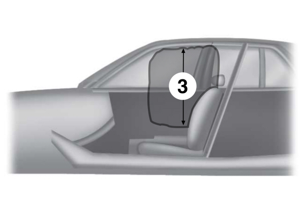
Figure 5 - Side View of the Side Airbag at Full Inflation- if equipped
| 3. |
Figure 6 - Side View of the Side Curtain Dimension
| 1. |
Note:
Do not place objects on the headliner or on pillar trims A through C used to conceal the airbag when stowed.
Figure 7 - Front View of the Side Curtain at Full Inflation
| 1. |
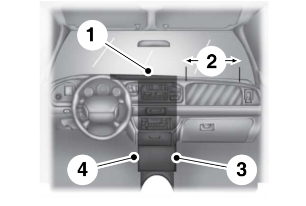
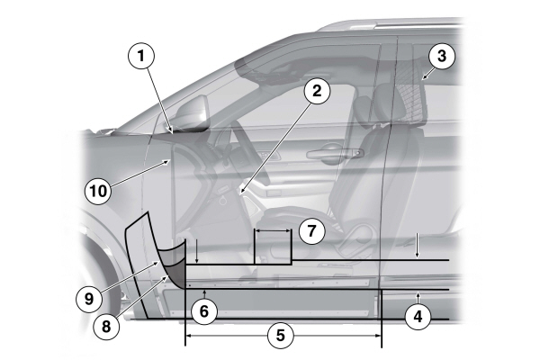
Figure 8 - Equipment Mounting Zones
| 1. 2. 3. 4. |
Figure 9 - Equipment Mounting Zones
| 1. 2. 3. 4. 5. 6. 7. 8. 9. 10. |
Figure 10 - Top View of the Equipment Mounting Zones
| 1. 2. 3. |
Thank You For Your Feedback