This bulletin supersedes 18-2179. Reason for update: Concern Carryover to New Model
Ford 2013-2020 Transit Connect |
Summary
This article supersedes TSB 18-2179 to update the model years affected.
Issue:
Some 2013-2020 Transit Connect vehicles built on or after 1-Jan-2013 may exhibit a condition where either section of the second row seat is stuck or difficult to fold or unfold. This may be due to a misrouted cable or a cable that is in need of adjustment. It may be necessary to reduce the cable end fitting length. It is not necessary to install a new second row seat.
Action:
Follow the Service Procedure steps to correct the condition on vehicles that meet all of the following criteria:
•
2013-2020 Transit Connect
•
Built on or after 1-Jan-2013
•
Long wheelbase
•
Either section of the 60/40 second row seat is stuck or difficult to fold or unfold
Warranty Status: Eligible under provisions of New Vehicle Limited Warranty (NVLW)/Service Part Warranty (SPW)/Special Service Part (SSP)/Extended Service Plan (ESP) coverage. Limits/policies/prior approvals are not altered by a TSB. NVLW/SPW/SSP/ESP coverage limits are determined by the identified causal part and verified using the OASIS part coverage tool. | Description | Operation No. | Time | | 2013-2020 Transit Connect: Inspect And Remove The 60% Or 40% Seat And Perform Service Procedure To Adjust (Do Not Use With Any Other Labor Operations) | 202047A | 0.7 Hrs. | | 2013-2020 Transit Connect: Inspect And Remove Both The 60% And 40% Seats And Perform Service Procedure To Adjust (Do Not Use With Any Other Labor Operations) | 202047B | 1.2 Hrs. |
| Causal Part: | A040045 | | Condition Code: | 01 |
1. Is either section of the second row seat bottom stuck in the folded position and/or is the strap stuck and displaying the red indicator on the strap on the seat back? (Figure 1)
(1). Yes - proceed to Step 2.
(2). No - this article does not apply. Refer to WSM, Section 501-10B for normal diagnostics.
Figure 1
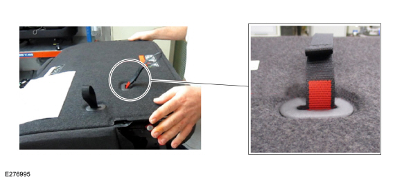
NOTE: The seat back will not fold when the seat bottom is stuck in the stowed position.
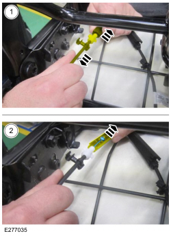
2. With the help of an assistant, gently pull/wiggle the adjuster cable(s) underneath the affected seat, while a second technician applies downward pressure to the seat back while pulling on the strap. (Figures 2-4)
(1). Make sure the driver seat is adjusted to the most forward position and the second row head rests are in the downward most position.
Figure 2
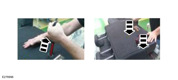
Figure 3
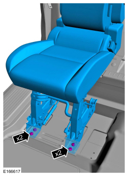
Figure 4
3. Remove the affected second row seat. Refer to WSM, Section 501-10B. (Figure 3, second row single seat shown, all others similar)
4. Place the seat on a workbench upside down to access the cable connectors below the seat cushion.
5. Open the cable connectors. (Figure 4)
(1). Mark the cables to ensure proper cable reinstallation.
(2). Remove the cable connector covers. (Figure 5)
(3). Remove the cable end from the cable connector. (Figure 5)
Figure 5
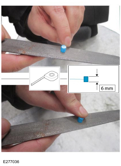
NOTE: Make sure to file the cable away from the seat to prevent contaminating the seat with metal shavings.
6. Using a Vernier caliper, measure the length of the head. The head should be a minimum of 6 mm (0.2362 in) long. (Figure 6)
(1). Using a file, reduce the end fitting on both sides to reduce the length of the head to achieve a minimum of 6 mm (0.2362 in) long. (Figure 7)
(2). Clean the cable end and seat area to remove shavings.
Figure 6
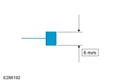
Figure 7
7. Repeat Step 6 for the remaining cable end.
8. Install the cable ends and covers.
9. Install the second row seat and tighten the bolts in the order below. Refer to WSM, Section 501-10B. Do not latch the seat to the body at this time. (Figure 8)
(1). Tighten both inner bolts to 45 Nm (33 lb-ft).
(2). Tighten both outer bolts to 45 Nm (33 lb-ft).
Figure 8
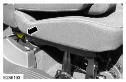
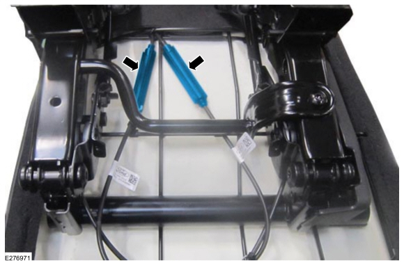
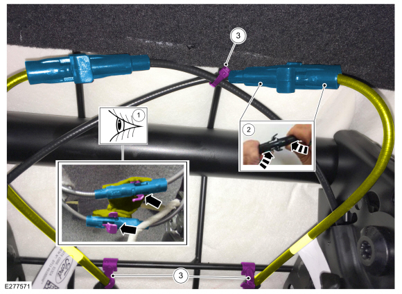
10. Locate the cable adjusters below the seat cushion. Release both cable adjusters. (Figure 9)
(1). Open one adjuster flap by pressing on the adjuster housing. Repeat this step for the opposite adjuster flap. (Figure 10, Callout 2)
Figure 9
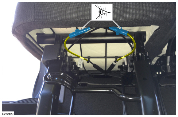
Figure 10
11. With both adjusters open, latch the seat to the body.
12. Close the adjusters.
13. Make sure the cable is secured to the seat bottom with tie straps. If not, secure the cable with tie straps as needed. (Figure 10, Callout 3)
|