This bulletin supersedes 22-2051.
Summary
This article supersedes TSB 22-2051 to update the vehicle model years affected.
Issue:
Some 2019-2023 Ranger vehicles may exhibit a shudder/vibration when accelerating from a stop. This may be due to an excessive rear axle pinion angle. To correct the condition, follow the Service Procedure steps to adjust the rear axle pinion angle.
Action:
Follow the Service Procedure to correct the condition on vehicles that meet all of the following criteria:
•
2019-2023 Ranger
•
Shudder/vibration when accelerating from a stop
| Service Part Number | Package Order Quantity | Description | | KB3Z-4C088-BKB3Z-4C088-B | 1 | Shim Kit |
| General Equipment: Digital Inclinometer General Equipment: Vehicle/Axle Stands General Equipment: Transmission Jack |
Warranty Status: Eligible under provisions of New Vehicle Limited Warranty (NVLW)/Service Part Warranty (SPW)/Service Part New Vehicle (SPNV)/Extended Service Plan (ESP) coverage. Limits/policies/prior approvals are not altered by a TSB. NVLW/SPW/SPNV/ESP coverage limits are determined by the identified causal part and verified using the OASIS part coverage tool. | Description | Operation No. | Time | | 2019-2023 Ranger: Verify Front Ride Height And Rear Axle Pinion Angle Includes Time To Install Shim Kit Following The Service Procedure (Do Not Use With Any Other Labor Operations) | 232078A | 0.9 Hrs. |
| Causal Part: | 4001 | | Condition Code: | 07 |
1. Park the vehicle on a level surface such as a drive-on hoist or alignment rack.
2. Verify the front and rear ride height is within specification per Workshop Manual (WSM), Section 204-00. Is the ride height within specification?
(1). Yes - proceed to Step 3.
(2). No - this article does not apply. Refer to WSM, Section 204-00 for further diagnostics.
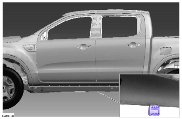
3. Calibrate the digital inclinometer by placing it on a clean, flat, and level section of the vehicle frame rail as indicated in Figure 1. Zero the tool.
NOTE: Do not use an analog dial gauge angle/finder protractor to measure rear axle pinion angle; an accurate reading will not be obtained. (Figure 1)
Figure 1
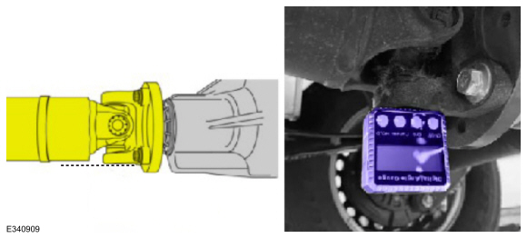
4. To simplify taking the measurements, rotate the driveshaft until the rear axle pinion flange yoke is parallel with the floor.
5. Take the rear axle pinion angle measurement from the horizontal face of the rear axle flange yoke and record as Angle A. (Figure 2)
Figure 2
6. Does the measurement read between 5.00 - 6.00 degrees?
(1). Yes - this article does not apply. Refer to WSM Section 205-01 for further diagnostics.
(2). No - proceed to Step 7.
7. Support the front of the vehicle. Use the General Equipment: Vehicle/Axle Stands.
8. Support the rear axle assembly. Use the General Equipment: Transmission Jack.
9. On both sides, remove and discard the rear shock absorber lower bolt and nut.
NOTE: Support the rear axle before removing the rear leaf spring U-bolts.
10. On both sides:
(1). Remove and discard the rear leaf spring U-bolt nuts.
(2). Remove the rear leaf spring U-bolt plates.
(3). Remove and discard the U-bolts.
11. Lower the axle assembly to gain access to the 1/4 in. (6 mm) spacer on the left side.
12. Remove and discard the 1/4 in. (6 mm) spacer on the left side.
NOTE: The service kit contains all of the parts necessary for the adjustment procedure. The rear axle pinion angle can be changed by adding a 0.5, 1, 1.5, or 2 degree rear axle pinion angle shims.
NOTE: Rear axle pinion shims provided in the kit are marked as LH and RH to identify the side of vehicle they are to be used. The thicker rear axle pinion shims are to only be used on the left side of the vehicle, and the thinner rear axle pinion shims on the right side.
NOTE: Only use 1 rear axle pinion shim per side.
NOTE: Make sure the rear axle pinion angle is between 5.00 – 6.00 degrees.
13. Install the desired rear axle pinion shims on the axle spring seats based on the calculation from Step 6.
(1). To decrease rear axle pinion angle, the thick edge of the rear axle pinion shim should be facing forward.
(2). To increase rear axle pinion angle, the thick edge of the rear axle pinion shim should be facing rearward.
NOTE: Make sure the word FRONT stamped on the part is facing rearward when increasing rear axle pinion angle.
14. Position and raise the rear axle.
NOTE: Tighten the rear spring U-bolts in a cross pattern with the vehicle resting on the wheels and tires (curb height).
15. On both sides:
(1). Position the new U-bolts onto the rear axle.
(2). Install the rear leaf spring U-bolt plates.
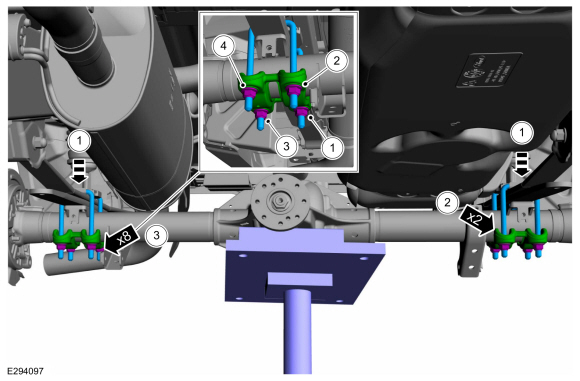
(3). Install the new rear leaf spring U-bolt nuts and tighten to 98 lb-ft (133 Nm). (Figure 3)
Figure 3
16. Position the rear shock absorber and install a new lower bolt and nut. Remove the transmission jack and tighten to 52 lb-ft (70 Nm).
17. Remove the support from the front of the vehicle.
NOTE: For additional information, refer to WSM Section 205-02.
NOTE: If the concern is still present, continue with normal diagnosis and repair.
|