Ford 2021-2023 Mustang Mach-E |
Issue:
Some 2021-2023 Mustang Mach-E vehicles may exhibit various driver assistance system warning messages or inoperative features and/or Diagnostic Trouble Code (DTC) U3000:49 stored in the Image Processing Module A (IPMA) that will not clear and not stored in the vehicle's history. DTC C1001:31 and/or U3000:89 may be stored in the IPMA, but may have recently been cleared and stored in the vehicle's history. This may be due to a connection issue between the IPMA Camera and the IPMA. To correct the condition, perform the following service procedure to repair the connection and reset the IPMA.
Action:
Follow the Service Procedure to correct the condition on vehicles that meet all of the following criteria:
•
2021-2023 Mustang Mach-E
•
IPMA has DTC U3000:49 present
•
At least one of the following concerns:
-
Front Camera Fault Service Required message
-
Pre-collision assist inoperative
-
Adaptive cruise control inoperative
-
Front windshield camera alignment routine fails to complete
| Service Part Number | Package Order Quantity | Number in Package | Description | | LJ8Z-14D202-VLJ8Z-14D202-V | If Needed | 1 | Image Processing Module A (IPMA) Camera to A-Pillar Coaxial Cable | | LJ8Z-14D202-WLJ8Z-14D202-W | If Needed | 1 | A-Pillar to IPMA Coaxial Cable (Built With Minor Feature Code HKLAG, HKLAH, And/Or J3QAD) | | LJ8Z-14D202-ULJ8Z-14D202-U | If Needed | 1 | A-Pillar to IPMA Coaxial Cable (Built With Minor Feature Code HKLAF And/Or J3QAA) | | ML3Z-19H406-BML3Z-19H406-B | If Needed | 1 | Image Processing Module A (IPMA) Camera | | 19H40519H405 | If Needed | 1 | Image Processing Module A (IPMA) - Refer To The Parts Catalog For The VIN Specific Application | | 164-R9343164-R9343 | As Needed | 1 | 3M™ Film Tape 9343 | | Obtain LocallyObtain Locally | As Needed | | Zip Ties |
Quantity refers to the amount of the service part number required to repair the vehicle. Unit of Issue refers to the number of individual pieces included in a service part number package. Piece Quantity refers to the total number of individual pieces required to repair the vehicle. As Needed indicates the amount of the part may vary and/or is not a whole number. Parts can be billed out as non-whole numbers, including less than 1. If Needed indicates the part is not mandatory. | Description | Operation No. | Time | | 2021-2023 Mustang Mach-E: Retrieve DTCs Inspect And Repair Following The Service Procedure (Do Not Use With Any Other Labor Operations) | MT232137 | Actual Time Up To 3.3 Hrs. |
| Causal Part: | 14D202 | | Condition Code: | B4 |
1. Is DTCs C1001:31 and/or U3000:89 stored in the IPMA?
(1). Yes - inspect the coaxial cables between the IPMA and the IPMA camera for loose connections. Perform a wiggle test to check C900 and C9128 connectors for loose connections. If no loose connections are present, proceed to Step 2. If loose connections are present, reconnect and proceed to Step 3.
(2). No - proceed to Step 27.
2. Power the vehicle on and wait 30 seconds. Clear and retrieve the DTCs. Is C1001:31 and/or U3000:89 present in the IPMA?
(1). Yes - proceed to Step 4.
(2). No - the issue is intermittent. Replace both sections of coaxial cable running from the IPMA Camera to the IPMA following Steps 4-15 and Steps 17-24, then proceeding to Step 25.
3. Power the vehicle on and wait 30 seconds. Clear and retrieve DTCs. Are C1001:31 and/or U3000:89 present in the IPMA?
(1). Yes – proceed to Step 4.
(2). No – proceed to Step 27.
4. Replace the coaxial cable running from the IPMA camera to the A-pillar by overlaying the new coaxial cable next to the existing coaxial cable and cutting off the existing coaxial cable connectors. To do so, begin by removing the left A-Pillar Trim Panel. Refer to Workshop Manual (WSM), Section 501-05 Interior Trim and Ornamentation, Removal and Installation, A-Pillar Trim Panel.
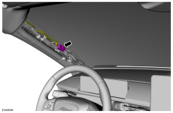
5. Disconnect the left headliner wiring harness found in A-pillar. (Figure 1)
Figure 1
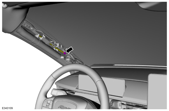
6. Disconnect left rear washer hose. (Figure 2) Refer to WSM, Section 501-16 Wipers and Washers, General Procedures, Washer Hose Coupling.
Figure 2
7. Remove move both sun visors. (Figure 3)
Figure 3
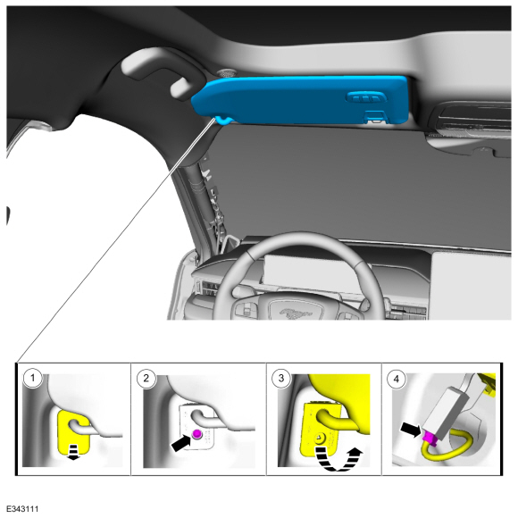
(1). Position the sun visor screw cover aside.
(2). Remove the sun visor screw.
(3). Rotate the sun visor downward.
(4). Disconnect the sun visor electrical connector.
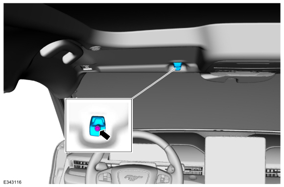
8. Remove the sun visor clips and screws from both sides. (Figure 4).
Figure 4
9. Remove the rear view mirror cover by releasing the clips holding the rear view mirror cover in place. (Figure 5)
Figure 5
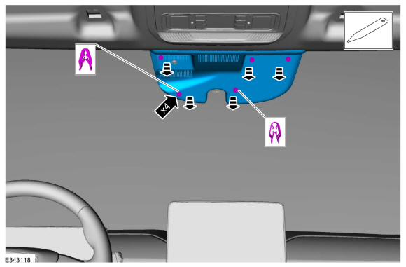
10. Disconnect C9128 connector going to the IPMA camera from the headliner.
11. Remove the front assist handles from both sides. (Figure 6)
Figure 6
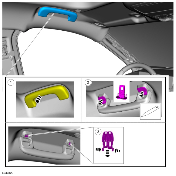
(1). Position the front assist handle down.
(2). Remove the front assist handle retainers.
(3). Remove the front assist handle clips.
12. Tuck the replacement coaxial cable into the headliner behind the headliner harness and use 3M™ film tape to overlay the new coaxial cable next to the existing coaxial cable. (Figure 7) Use 3M™ film tape (not zip ties) to overlay the cable in the headliner and A-pillar. Using zip ties with sharp cuts near the side curtain airbag may impede the airbag’s performance once installed. (Figure 8)
Figure 7
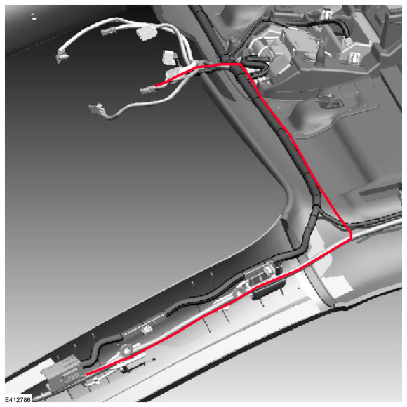
Figure 8
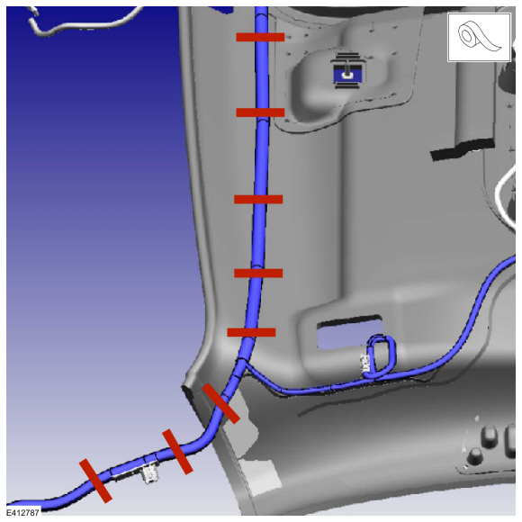
NOTE: Do not kink or route the cable in such a way that it bends greater than 90 degrees over 30 mm (1.2 in). Sharp bends could damage the cable. Press the 3M™ film tape firmly to the headliner to make sure the tape adheres to the headliner.
13. On the male side of the headliner wiring harness electrical connector (C900), remove the existing coaxial cable pin from the connector, and install the coaxial pin from the newly installed coaxial cable. Refer to Wiring Diagram, Connector Views, C900. (Figure 9)
Figure 9
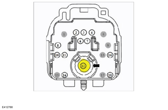
14. Reattach headliner to the roof using the headliner magnets. Install a new C9128 connector to the IPMA camera and reconnect the headliner wiring harness electrical connector. Refer to Figures 10-11. Cut the existing coaxial cable connectors to make sure the original cable is not used again.
Figure 10
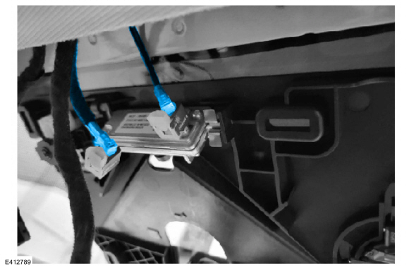
Figure 11
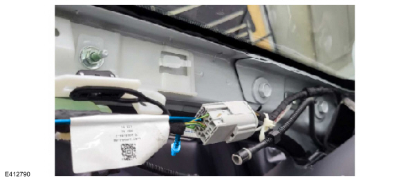
15. Install the newly overlaid harness in A-pillar back onto the A-pillar mounting bracket, above the fasteners that hold the bracket in place. (Figure 12)
Figure 12
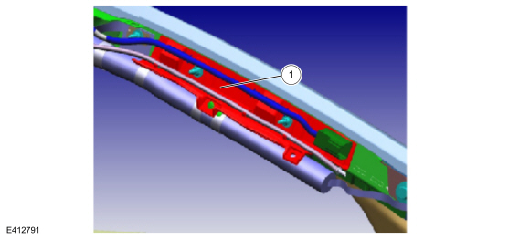
NOTE: Make sure to correctly install the headliner harness onto the bracket to avoid impeding the side curtain airbag.
16. Power the vehicle on and wait 30 seconds. Clear and retrieve the DTCs. Is C1001:31 and/or U3000:89 present in the IPMA?
(1). Yes – proceed to Step 17 to replace the coaxial cable running from A-Pillar to IPMA by overlaying the new coaxial cable next to the existing coaxial cable and cutting off the existing coaxial cable connectors.
(2). No - proceed to Step 27.
17. Remove the left A-pillar trim panel if not already removed. Refer to WSM, Section 501-05 Interior Trim and Ornamentation, Removal and Installation, A-Pillar Trim Panel.
18. On the left side, disconnect the headliner wiring harness electrical connector (C900). (Figure 1)
19. Remove the left B-pillar trim panel. Refer to WSM, Section 501-05 Interior Trim and Ornamentation, Removal and Installation, B-Pillar Trim Panel.
20. Remove the left loadspace trim panel. Refer to WSM, Section 501-05 Interior Trim and Ornamentation, Removal and Installation, Loadspace Trim Panel.
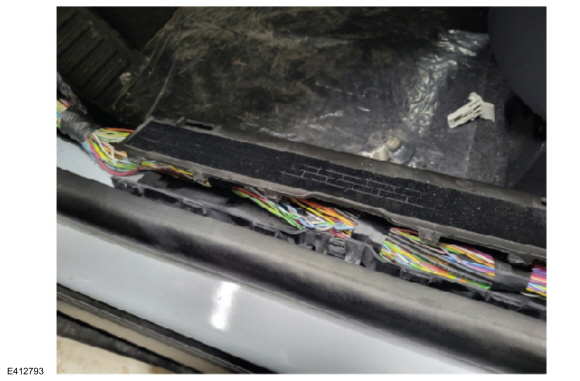
21. Remove the left side body harness scuff plates located under the front scuff plate trim panel rear scuff plate trim panel. (Figures 13-14)
Figure 13
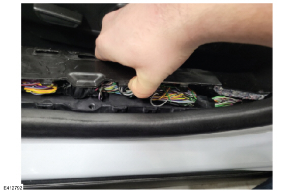
Figure 14
22. Is the vehicle equipped with minor feature codes HKLAG, HKLAH, and/or J3QAD? To confirm a vehicle is built with any of these minor feature codes, review the build information by double-clicking the vehicle identification number (VIN) in the upper left-hand corner on the Professional Technician System (PTS) website.
(1). Yes - the replacement coaxial cable comes with an additional jumper that goes to a C2563 connector for the accessory protocol interface module (APIM). For these vehicles, also remove the driver side floor console front trim panel, passenger side footwell trim panel, and passenger side floor console front trim panel. Refer to WSM, Section 501-12 Instrument Panel and Console, Removal and Installation.
(2). No - proceed to Step 23.
23. Using small zip ties, overlay the new coaxial cable next to the existing 14335 harness. (Figures 15–18) If extra cable length is present when routing the new coaxial cable, loop and stow the excess length. (Figure 18)
Figure 15
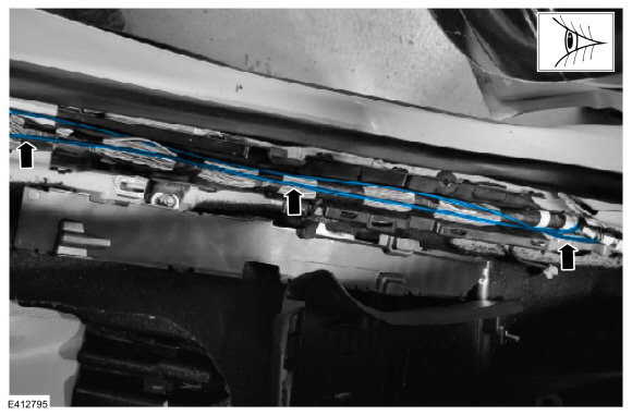
Figure 16
Figure 17
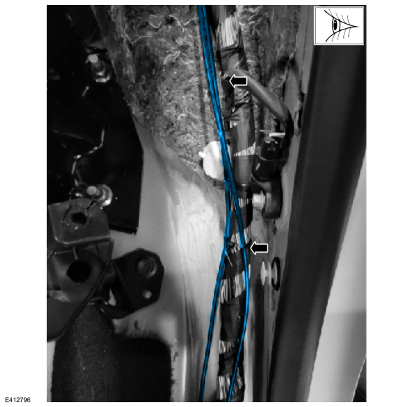
Figure 18
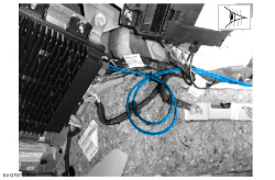
NOTE: Do not kink or route the cable in such a way that it bends greater than 90 degrees over 30 mm (1.2 in). Sharp bends could damage the cable.
24. Is the vehicle equipped with Minor Feature Codes HKLAG, HKLAH, and/or J3QAD? To confirm a vehicle is built with a certain minor feature code, review the build information by double-clicking the vehicle identification number (VIN) in the upper left-hand corner on the Professional Technician System (PTS) website.
(1). Yes - using small zip ties, overlay the new coaxial cable jumper to the C2563 connector found in the passenger footwell. (Figures 19-21) Once the new C2563 connector is in place, cut off original coaxial cable connectors. If extra cable length is present when routing the new coaxial cable, loop and stow the excess length. (Figure 21)
NOTE: Do not kink or route the cable in such a way that it bends greater than 90 degrees over 30 mm (1.2 in). Sharp bends could damage the cable.
Figure 19
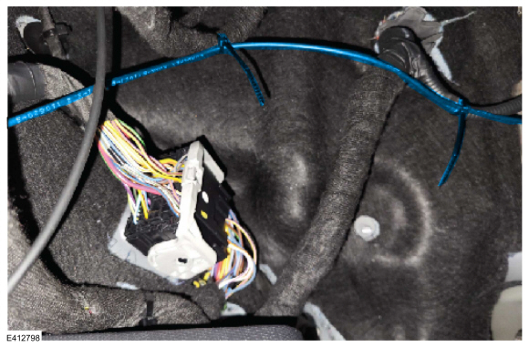
Figure 20
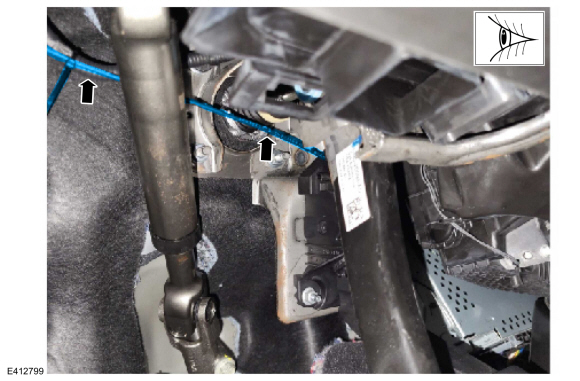
Figure 21
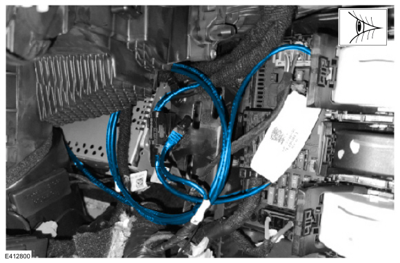
(2). (2) No - proceed to Step 25.
25. Power the vehicle on and wait 30 seconds. Clear and retrieve the DTCs. Is C1001:31 and/or U3000:89 present in the IPMA?
(1). Yes - replace the IPMA camera. Refer to WSM, Section 419-07 Lane Keeping System, Removal and Installation, Image Processing Module A (IPMA) Camera.
(2). No - proceed to Step 27.
26. Power the vehicle on and wait 30 seconds. Clear and retrieve the DTCs. Is C1001:31 and/or U3000:89 present in the IPMA?
(1). Yes - replace the IPMA. Refer to WSM, Section 419-07 Lane Keeping System, Removal and Installation, Image Processing Module A (IPMA).
(2). No - proceed to Step 27.
27. Is DTC U3000:49 stored in the IPMA?
(1). Yes - download and run the IPMA - Reset the Image Processing Module A (IPMA) Learned Values application in the Ford Diagnosis and Repair System (FDRS). Then run the IPMA - Image Processing Module A (IPMA) Alignment application immediately after. If U3000:49 is still present after completing the IPMA - Reset the Image Processing Module A (IPMA) Learned Values application, then replace the IPMA. Refer to WSM, Section 419-07 Lane Keeping System, Removal and Installation, Image Processing Module A (IPMA).
(2). No - repair is complete.
|