This bulletin supersedes 22-2278.
Ford 2020-2023 Escape | Lincoln 2020-2023 Corsair |
Summary
This article supersedes TSB 22-2278 to update the vehicle model years affected and the part list.
Issue:
For 2020-2023 Escape/Corsair vehicles, the roof opening panel frame mechanism kits have been released for service. These components can now be serviced separately and no longer require replacement of the entire roof opening panel frame. To correct the condition, follow the Service Procedure to install the roof opening panel frame mechanism kit.
Action:
Follow the Service Procedure to correct the condition on vehicles that meet the following criteria:
•
2020-2023 Escape/Corsair
•
Equipped with roof opening panel
•
One or more of the following symptoms related roof opening panel mechanism failure:
-
Glass misalignment
-
Popping/creaking noise
-
Slow opening/closing
-
Binding
-
Wind noise
| Service Part Number | Claim Quantity | Package Order Quantity | Number in Package | Description | | GD9Z-5400817-AGD9Z-5400817-A | 2 | 2 | 1 | Retainer Clip | | LJ6Z-7851070-ALJ6Z-7851070-A | 1 | 1 | 1 | Service Guide Assembly With Mechanism Kit, Right (Escape) | | LJ6Z-7851071-ALJ6Z-7851071-A | 1 | 1 | 1 | Service Guide Assembly With Mechanism Kit, Left (Escape) | | LJ7Z-7851070-ALJ7Z-7851070-A | 1 | 1 | 1 | Service Guide Assembly With Mechanism Kit, Right (Corsair) | | LJ7Z-7851071-ALJ7Z-7851071-A | 1 | 1 | 1 | Service Guide Assembly With Mechanism Kit, Left (Corsair) |
Quantity refers to the amount of the service part number required to repair the vehicle. Unit of Issue refers to the number of individual pieces included in a service part number package. Piece Quantity refers to the total number of individual pieces required to repair the vehicle. Warranty Status: Eligible under provisions of New Vehicle Limited Warranty (NVLW)/Service Part Warranty (SPW)/Service Part New Vehicle (SPNV)/Extended Service Plan (ESP) coverage. Limits/policies/prior approvals are not altered by a TSB. NVLW/SPW/SPNV/ESP coverage limits are determined by the identified causal part and verified using the OASIS part coverage tool. | Description | Operation No. | Time | | 2020-2023 Escape/Corsair: Replace Both Guide Assemblies Includes Time To Lower Headliner (Do Not Use With Any Other Labor Operations) | 232139A | 4.6 Hrs. |
| Causal Part: | 5450056 | | Condition Code: | 01 |
1. Remove the roof opening panel glass assembly. Refer to Workshop Manual (WSM), Section 501-17 Roof Opening Panel > Removal and Installation > Roof Opening Panel Glass.
2. Remove the air deflector assembly. Refer to WSM, Section 501-17 Roof Opening Panel, Removal and Installation > Air Deflector.
3. Lower the headliner. Refer to WSM, Section 501-05.
4. Remove the air deflector panel by removing the 3 button head screws attaching the panel to the roof opening panel frame.
5. Reconnect both A-Pillar electrical connectors and over head console electrical connectors.
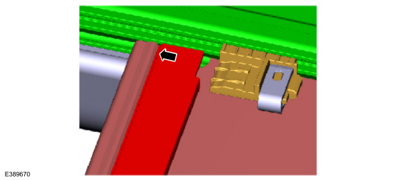
6. Disengage the sunshade crossbar from the sunshade drive cable plate.
(1). Position the sunshade in the center of the roof opening.
(2). Disengage the sunshade crossbar from the sunshade drive cable plates left and right side. (Figure 1)
Figure 1
7. Disengage the fabric pilot clips from the sunshade drive cable plate. (Figure 2)
Figure 2
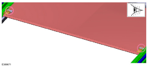
(1). The sunshade is under tension. Hold the cross bar when releasing the second fabric pilot clip to prevent the roller from pulling the fabric, clips and cross bar into the sunshade bracket assembly.
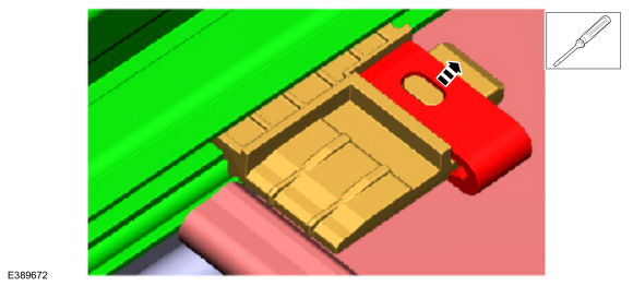
(2). Using a small flat bladed screwdriver, lift the tab off of the locking button and slide the clip rearward to release the fabric pilot clips from the sunshade drive cable plates left and right side. (Figure 3)
Figure 3
(3). Slide the fabric and pilot clips rearward until they are fully out of the track.
8. Starting with left side, remove the 2 button head screws and remove the front inside locator on the left side. (Figures 4-5)
Figure 4
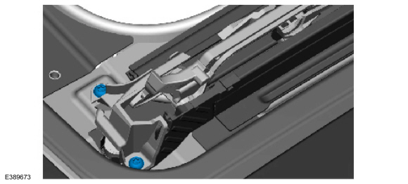
Figure 5
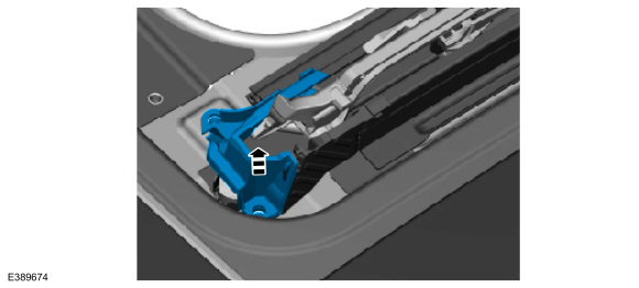
9. Remove the left mechanism bracket. (Figures 6)
Figure 6
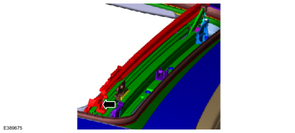
(1). Make sure the mechanism is in the partial open position.
1. Partial open is the position where the glass begins the slide motion immediately after vent.
(2). Disengage the front slide shoe (mechanism bracket) from the front inside locator. (Figure 7)
Figure 7
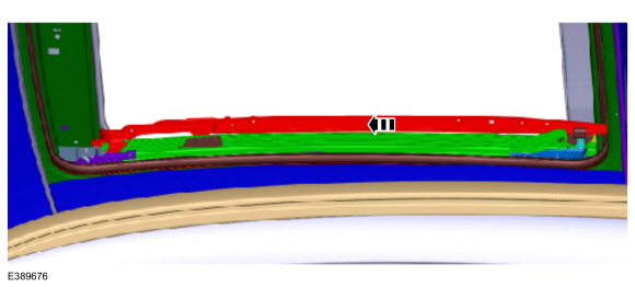
(3). Slide the mechanism bracket assembly forward until it is fully disengaged from the driving wedge (rear locator assembly). (Figure 8)
Figure 8
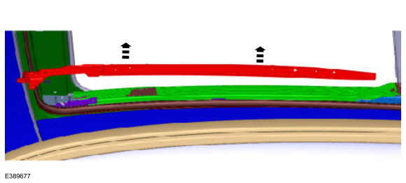
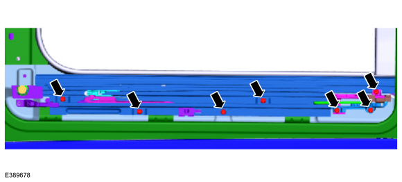
10. Remove the 7 button head screws - top side. (Figure 9)
Figure 9
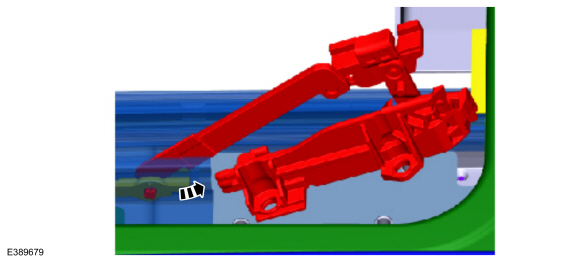
11. Remove the left rear locator assembly.
(1). Disengage the rear locator assembly from the guide by applying a gentle rearward force near the forward screw location. (Figure 10)
Figure 10
(2). Rotate the rear locator assembly counterclockwise until the connection bar can be disengaged from the control slide. (Figure 11-12)
Figure 11
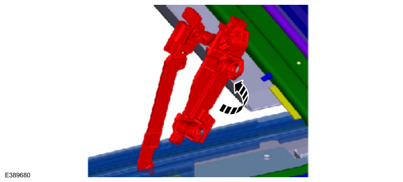
Figure 12
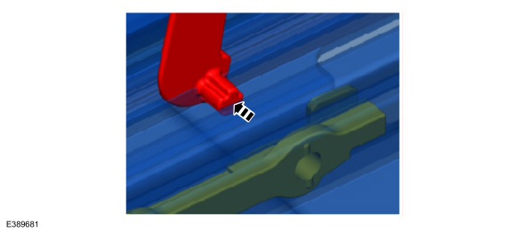
12. Remove the 2 button head screws – bottom side. (Figure 13)
Figure 13
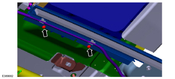
 WARNING: Protective gloves are recommended for Step 13. WARNING: Protective gloves are recommended for Step 13.
13. Disengage the left relief tube and clips from the guide (2 clips on the left side; 3 clips on the right side) (Figure 14)
Figure 14
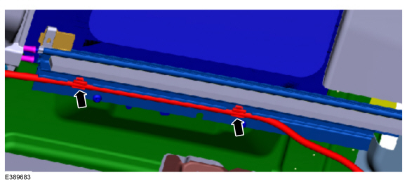
14. Remove the left guide assembly.
(1). Rotate the front of the guide assembly upward and inward.(Figure 15)
Figure 15
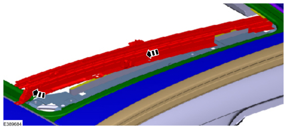
(2). Slowly pull the guide assembly forward releasing the guide assembly from the drive cables.
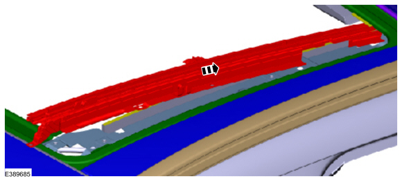
15. Install the new left guide assembly.
(1). Starting at the rear end of the guide, slowly feed the drive cables into the guide and align the guide screw positions to the holes in the frame. (Figure 16)
Figure 16
16. Re-engage the left relief tube to the clips. (Figure 17)
Figure 17
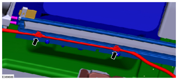
17. Repeat Steps 8-16 on the right side.
18. Install the button head screws finger tight.
19. Set the guide-to-guide alignment. (Figure 18)
Figure 18
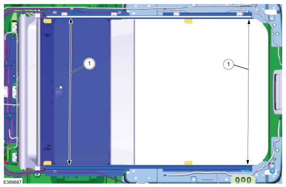
(1). Use a measuring device to set the guide alignment (730.46 mm ± 0.6 mm, 2 locations).
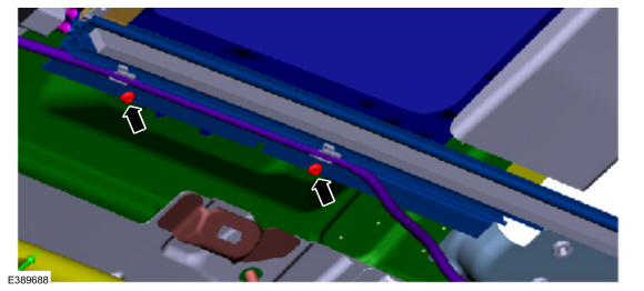
20. Tighten the 2 button head screws - bottom side (left and right side) to 5.0 Nm ± 0.5 Nm. (Figure 19)
Figure 19
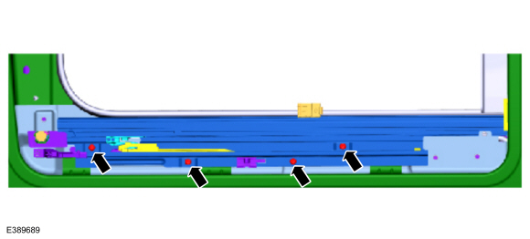
21. Tighten the 4 button head screws - top side (left and right side) to 5.0 Nm ± 0.5 Nm. (Figure 20)
Figure 20
22. Verify the guide alignment and adjust as needed. (Figure 18)
(1). Use a measuring device to verify the guide alignment (730.46 mm ± 0.6 mm, 2 locations).
23. Starting with the left side, verify the new rear locator assembly on the left side.
(1). Verify that the assembly rear lever is in the vertical position and that the slide pins are engaged in the proper channels. (Figure 21)
Figure 21
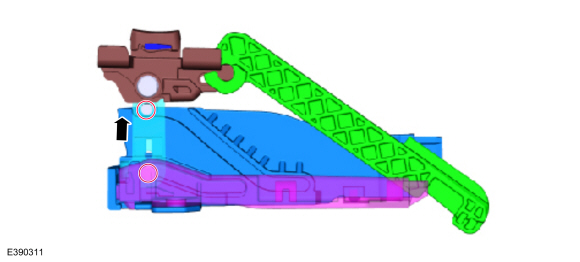
(2). Verify that the locator rear inside is properly engaged to the locator rear outside. (Figure 22-24)
Figure 22
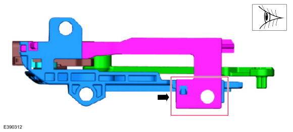
Figure 23
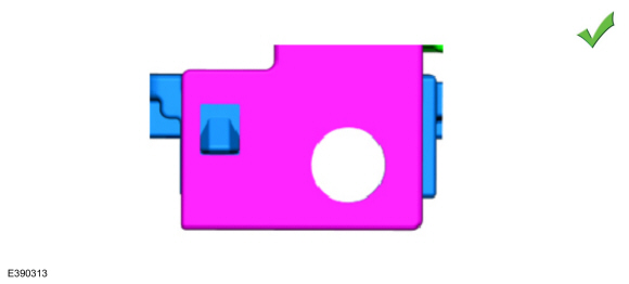
Figure 24
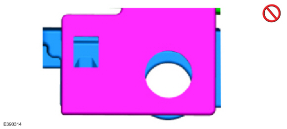
24. Install the new left rear locator assembly.
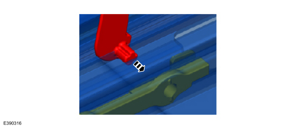
(1). Attach the connection bar to the control slide. (Figure 25-26)
Figure 25
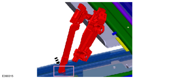
Figure 26
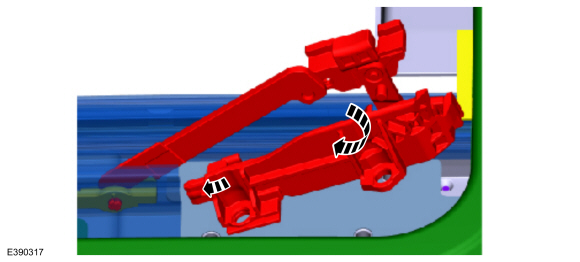
(2). Rotate the rear locator assembly clockwise until the front tab of the rear locator assembly can be installed into the guide. (Figure 27)
Figure 27
(3). Verify that the hard stop feature of the rear locator assembly is fully engaged to the guide.(Figures 28-29)
Figure 28
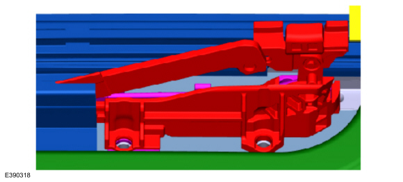
Figure 29
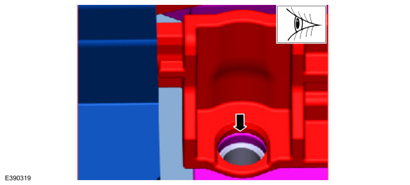
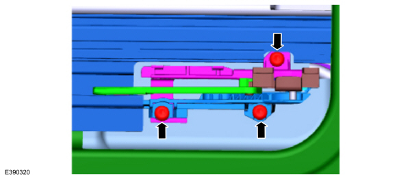
25. Tighten the 3 button head screws to 3.5 Nm ± 0.3 Nm. (Figure 30)
Figure 30
26. Install the new left mechanism bracket assembly.
(1). Install the mechanism bracket assembly (rear end) into the driving wedge. (Figure 31)
Figure 31
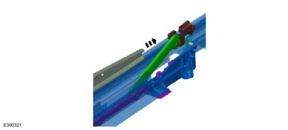
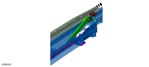
(2). Continue to slide the mechanism bracket rearward. (Figure 32)
Figure 32
(3). Rotate the front lever downward so that it is perpendicular to the mechanism bracket arm. (Figures 33-34)
Figure 33
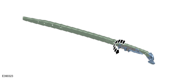
Figure 34
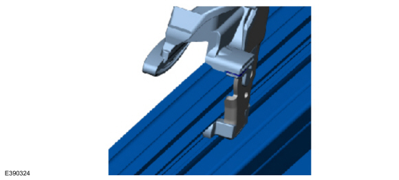
(4). Insert the front lever foot into the guide channel. (Figure 35)
Figure 35
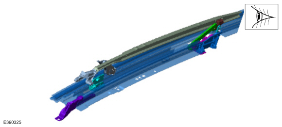
(5). Rotate the mechanism bracket forward (and downward). (Figures 36-37)
NOTE: Make sure the front slide shoes of the mechanism bracket move in front of the guide, the outside foot must engage into the front outside locator channel.
Figure 36
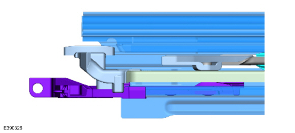
Figure 37
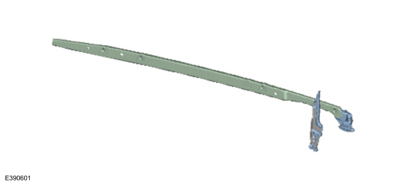
(6). The front lever must engage into the driven slider.
(7). Slide the mechanism bracket rearward so that the slide shoe features enter into their respective guide channels.
27. Install the front inside locator.
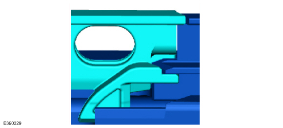
(1). Verify that the front inside locator is properly engaged to guide.(Figure 38)
Figure 38
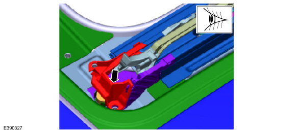
(2). Tighten the 2 button head screws to 3.5 Nm ± 0.3 Nm. (Figures 39-40)
Figure 39
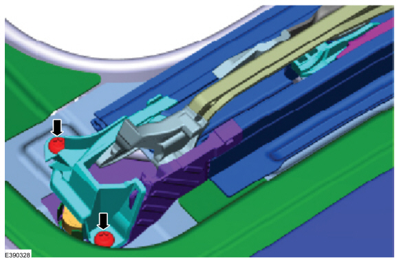
Figure 40
28. Repeat Steps 23-27 on the right side.
29. Install the air deflector panel to the roof opening panel frame.
(1). Tighten the 3 button head screws to 3.5 Nm ± 0.3 Nm.
30. Install the air deflector assembly. Refer to WSM, Section 501-17 Roof Opening Panel, Removal and Installation > Air Deflector.
31. Install the fabric pilot (left and right sides). Refer to WSM, Section 501-17 Roof Opening Panel, Removal and Installation > Installation > Only Step 22-24.
32. Install the sunshade cross bar onto the drive cables. Refer to WSM, Section 501-17 Roof Opening Panel, Removal and Installation > Installation > Only Step 25-26.
33. Install the roof opening panel glass assembly. Refer to WSM, Section 501-17 Roof Opening Panel > Removal and Installation > Roof Opening Panel Glass.
34. Install the headliner. Refer to WSM, Section 501-05.
35. Verify the glass and sunshade are operating properly.
(1). Verify no operational failures or appearance failures such as false reversal, sunshade derails/wrinkles, mechanism click.
|